- Shopping, made easy.
- /
- Get the app!
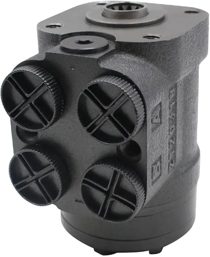
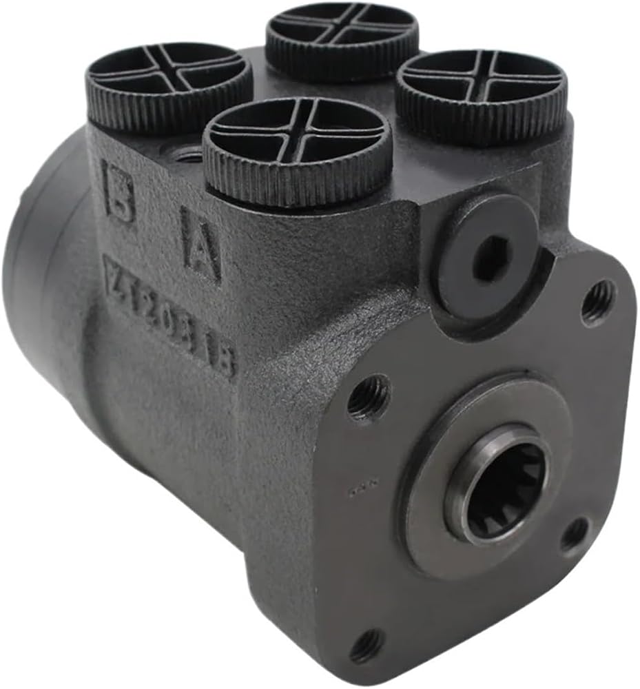
101S-1,2,4 Series Hydraulic Steering Control Units (SCU)
Parameters
Type 101S-*-***-*
Function Code
1,2,4
Displacement (mL/r)
50
63
80
100
125
160
200
Rated flow (L/min)
5
6
8
10
12.5
16
20
Max.input pressure (MPa)
17.5
Relief Valve Pressure Settings(Mpa)
06,07,08,10,12,14,15,16,17.5
Shock Valves Pressure Settings(Mpa)
12,13,14,16,18,20,21,22,23.5
Max. cont. back pressure (MPa)
2.5
Weight (kg)
5.75
5.81
5.89
5.96
6.1
6.3
6.5
Dimension L (mm)
130
132
134
137
140
145
150
Parameters
Type 101S-*-***-*
Function Code
1,3
Displacement (mL/r)
250
280
315
400
Rated flow (L/min)
25
28
31.5
40
Max.input pressure (MPa)
17.5
Relief Valve Pressure Settings(Mpa)
06,07,08,10,12,14,15,16,17.5
Shock Valves Pressure Settings(Mpa)
12,13,14,16,18,20,21,22,23.5
Max. cont. back pressure (MPa)
2.5
Weight (kg)
6.68
6.86
7.06
7.45
Dimension L (mm)
156
161
166
176
The installation and use of full hydraulic steering note
1 installation precautions:
* (1) When installation steering gear must ensure coaxiality with column, must have a gap of 1 mm in the axial direction.
* (2) The depth of screw connection to the steering column tightening steering column is 15mm.
* (3) After steering gear installed, must check steering wheel turns to ensure the flexibility of the return position.
* (4) Connection pipeline: P oil port connects to the oil supply pump, T oil port connects to the oil tank, and A and B oil portsrespectively connect the left and right oil chambers of the steering gear.
2 oil flow rate considerations:
* (1) The oil supply circuit connected to the P oil port, the oil flow rate in the pipe is recommended to be 1.5m/s.
* (2) The pressure circuit of the
 CAARLA Hydraulic Steering Gear Control Unit Orbit OSPC Pump Hydraulic Parts Steering Vehicle Orbitrol Steering
SAR 2,450
CAARLA Hydraulic Steering Gear Control Unit Orbit OSPC Pump Hydraulic Parts Steering Vehicle Orbitrol Steering
SAR 2,450
 Hydraulic Steering Gear Steering Control Unit Orbit Steering Ospc 100 On
SAR 4,217
Hydraulic Steering Gear Steering Control Unit Orbit Steering Ospc 100 On
SAR 4,217
 CAARLA Hydraulic Steering Gear 101S-1-100-16-I Hydraulic Steering
SAR 4,022
CAARLA Hydraulic Steering Gear 101S-1-100-16-I Hydraulic Steering
SAR 4,022
 Hydraulic Steering Gear Tractor AL41631 OSPC125CN Hydraulic Steering Unit
SAR 2,396
Hydraulic Steering Gear Tractor AL41631 OSPC125CN Hydraulic Steering Unit
SAR 2,396