- Shopping, made easy.
- /
- Get the app!
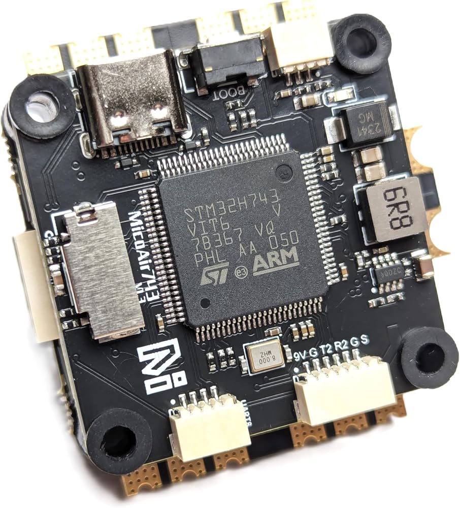
** H743 Flight controller, with dual IMU and compass sensor built-in, supports Ardupilot/PX4/INAV/Betaflight.**
Ardupilot
MicoAir H743 flight controller is officially supported by Ardupilot starting from version 4.6. You can update the firmware through Mission Planner or download all the firmware files (Copter/Heli/Plane/Rover/etc) here:
You can also use the online firmware builder provided by Ardupilot to customize your firmware for MicoAir743:
Old version (v4.5.1) firmware can be downloaded here:
User Manuals and Tutorials (updated in real-time)
PX4
MicoAir743 flight controller is officially supported by PX4 from version 1.15.0.
You can also download the firmware and bootloader built by us (1.13.3 & 1.14.0):
Betaflight
MicoAir743 flight controller is officially supported by Betaflight from version 4.5.0.
INAV
MicoAir743 is officially supported by INAV from version 8.0.0. You can also download the old version firmware built by us:
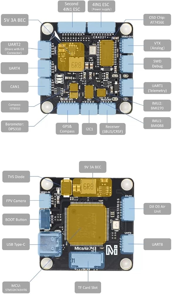
Specifications (FC)
MCU: STM32H743VIT6, 480MHz, 2MB Flash
IMU: BMI088/BMI270
Baro: DPS310
Compass: IST8310
OSD: AT7456E
MicroSD Card Slot
7x UART
10x PWM
1x CAN
1x I2C
1x SWD
2x ADC (VBAT, Current)
USB Type-C
BEC 5V 3A output (for controller, receiver, GPS, optical flow, or other devices)
BEC 9V 3A output (for video transmitter, camera)
UART Mapping (Ardupilot)
SERIAL0 -> USB
SERIAL1 -> UART1 (MAVLink2, DMA-enabled)
SERIAL2 -> UART2 (VTX-HD, DMA-enabled)
SERIAL3 -> UART3 (GPS, DMA-enabled)
SERIAL4 -> UART4 (MAVLink2, DMA-enabled)
SERIAL5 -> UART6 (RCIN, DMA–enabled)
SERIAL6 -> UART7 (ESC Telemetry, DMA-enabled)
SERIAL7 -> UART8 (DMA–enabled)
UART Mapping (PX4)
TEL1 -> UART1
TEL2 -> UART2
GPS1 -> UART3
TEL3 -> UART4
RC -> UART6
ESC -> UART7
TEL4 -> UART8
RC Input (Ardupilot)
The default RC input is configured on the UART6. The SBUS pin is inverted and connected to RX6. Non-SBUS, single-wire serial inputs can be directly tied to RX6 if the SBUS pin is left unconnected. RC could be applied instead at a different UART port such as UART2, UART4, or UART8, and set the protocol to receive RC data: SERIALn_PROTOCOL=23 and change SERIAL5 _Protocol to something other than ‘23'.
OSD Support (Ardupilot)
The MicoAir743 supports OSD using OSD_TYPE 1 (MAX7456 driver) and OSD_TYPE 5 (MSP_DISPLAYPORT).
VTX Support
The SH1.0-6P connector supports a DJI Air Unit / HD VTX connection. Protocol defaults to DisplayPort. Pin 1 of the connector is 9v, so be careful not to connect this to a peripheral requiring 5v.
PWM Output
The MicoAir743 supports up to 10 PWM outputs.
Channels 1-10 support DShot.
Channels 1-8 support bi-directional DShot.
(Currently, PX4 & INAV do not support BDShot function)
PWM output share grouped, and every group must use the same output protocol:
1,2,3,4 are group 1
5,6 are group 2
7,8,9,10 are group 3
Battery Monitoring
The board has an internal voltage sensor and connections on the ESC connector for an external current sensor input. The voltage sensor can handle up to 6S LiPo batteries. The default battery parameters (for Ardupilot) are:
BATT_VOLT_PIN 10
BATT_CURR_PIN 11
BATT_VOLT_MULT 21.2
BATT_CURR_SCALE 40.2
Compass
The MicoAir743 has a built-in compass sensor (IST8310), and you can also attach an external compass using I2C on the SDA and SCL connector.
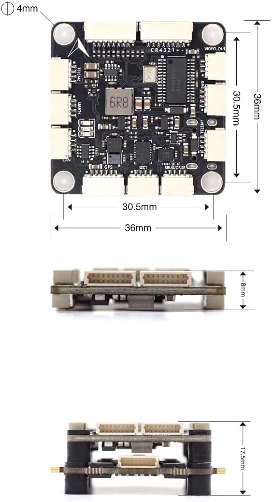
Physical
Mounting: 30.5 x 30.5mm, Φ4mm
Dimensions: 36 x 36 x 8 mm
Weight: 9g
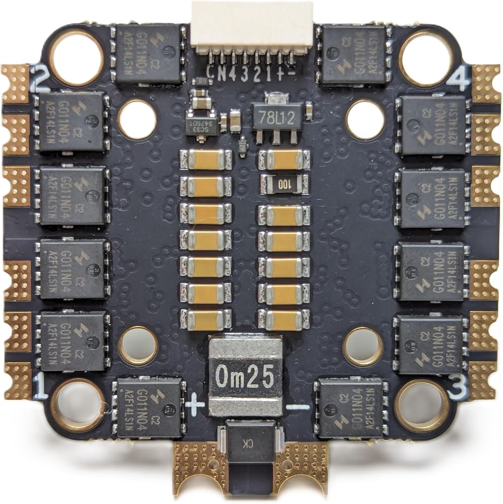
Specifications (ESC)
Input Voltage Range: 2-6S
Maximum Continuous Working Current: 50A
Current Sensor: Yes
ESC Firmware: BlueJay 48K
Firmware Version: v0.19.2
Control Signal Support: DShot150/300/600
Supports Bidirectional Dshot, Speed Feedback
Fixed Mounting Holes:
M4-30.5*30.5mm
M3-20*20mm
MOSFET Specifications: 40V 165A RDS=1.1mR
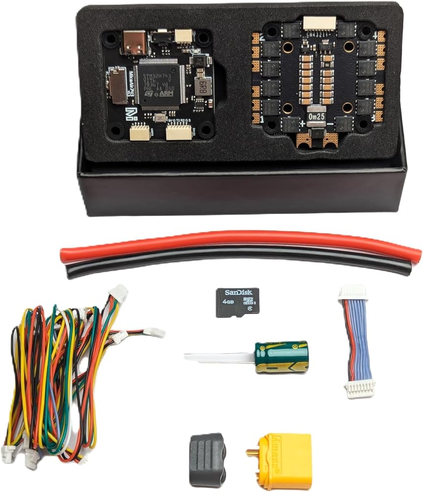
Package List:
MicoAir H743 Flight Controller (Ardupilot Firmware) * 1
4G TF Card *1
MicoAir 4 in 1 ESC * 1
12AWG Wiring *2
ESC Signal Wiring *1
Connecting Wiring *7
Capacitance *1
XT60 Plug * 1
Rubber Mat * 8
 Drone with camera, brushless motor, drone camera, quadcopter, foldable, electrically adjustable 1080P high-definition drone app, 3D flip, easy control
SAR 287
Drone with camera, brushless motor, drone camera, quadcopter, foldable, electrically adjustable 1080P high-definition drone app, 3D flip, easy control
SAR 287
 Mini 4 Pro Propeller Guard, Quick Release Removable Propeller Cover Anti-Collision Avoid Propellers Damage for DJI Mini 4 Pro
SAR 250
Mini 4 Pro Propeller Guard, Quick Release Removable Propeller Cover Anti-Collision Avoid Propellers Damage for DJI Mini 4 Pro
SAR 250
 Payload Drop Kit Dual Payloads with Emergency Lighting (Blue/Red) for DJI M30 Aircraft (all models)
SAR 3,748
Payload Drop Kit Dual Payloads with Emergency Lighting (Blue/Red) for DJI M30 Aircraft (all models)
SAR 3,748
 2025 New GPS Drone with Camera Screen on Controller Brushless Motor Foldable Mini 5G RC Quadcopter Drones for Adults Beginner, Support Gesture Control,Altitude Hold,Headless Mode (Black)
SAR 1,085
2025 New GPS Drone with Camera Screen on Controller Brushless Motor Foldable Mini 5G RC Quadcopter Drones for Adults Beginner, Support Gesture Control,Altitude Hold,Headless Mode (Black)
SAR 1,085