- Shopping, made easy.
- /
- Get the app!
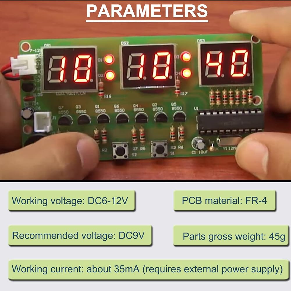
Parameters:
Working voltage: DC6-12V, recommended voltage: DC9V
Working current: about 35mA (requires external power supply)
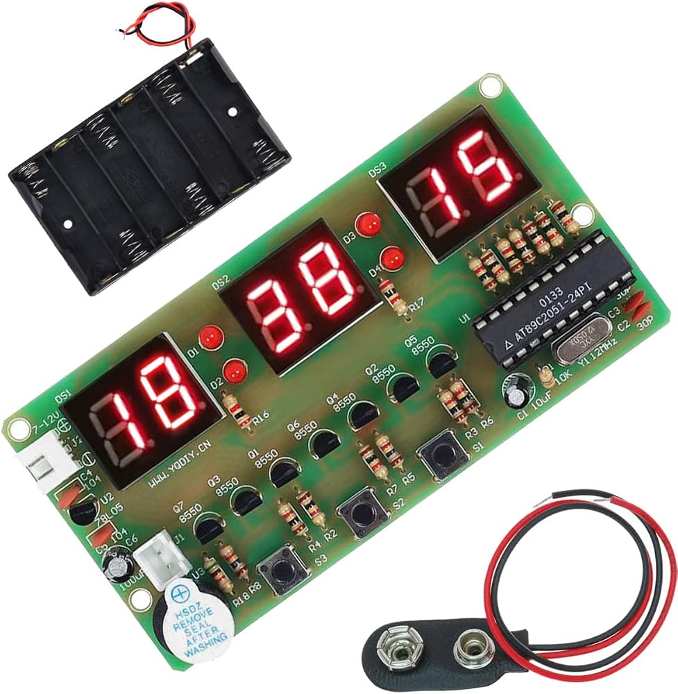
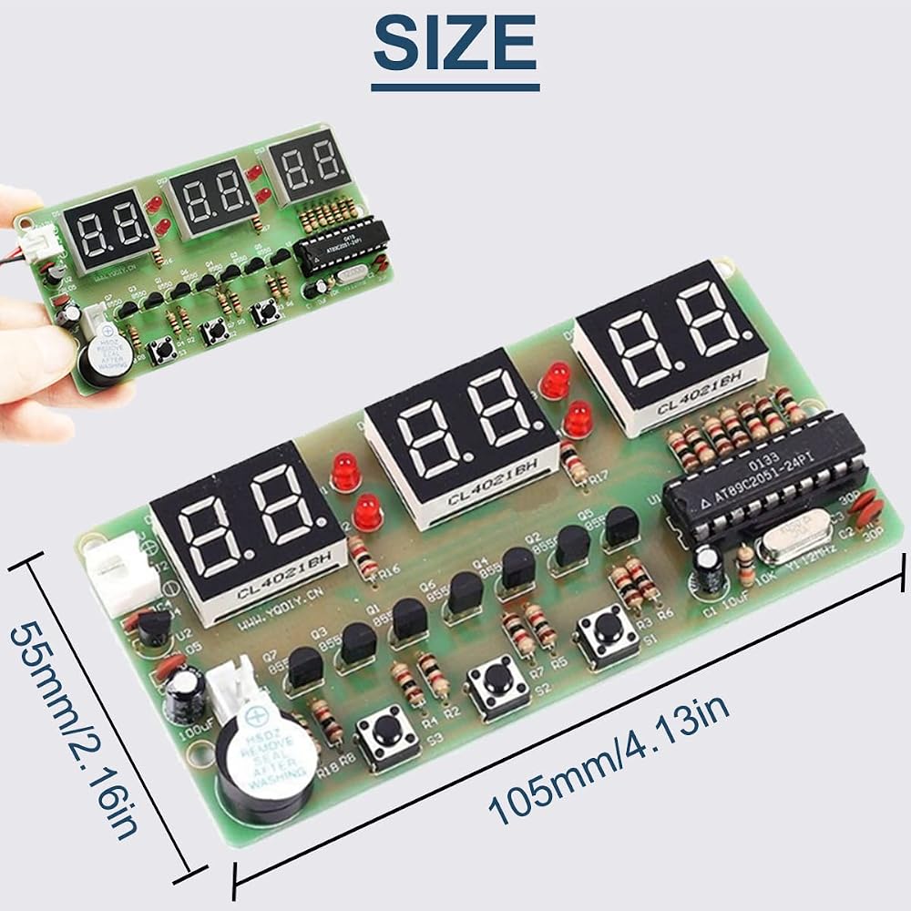
PCB material specification: FR-4, 105x55mm, thickness 1.6mm, double-sided UV green oil
Digital tube: 0.4 inch, red light, common anode type
Parts gross weight: 45g
Instructions for use:
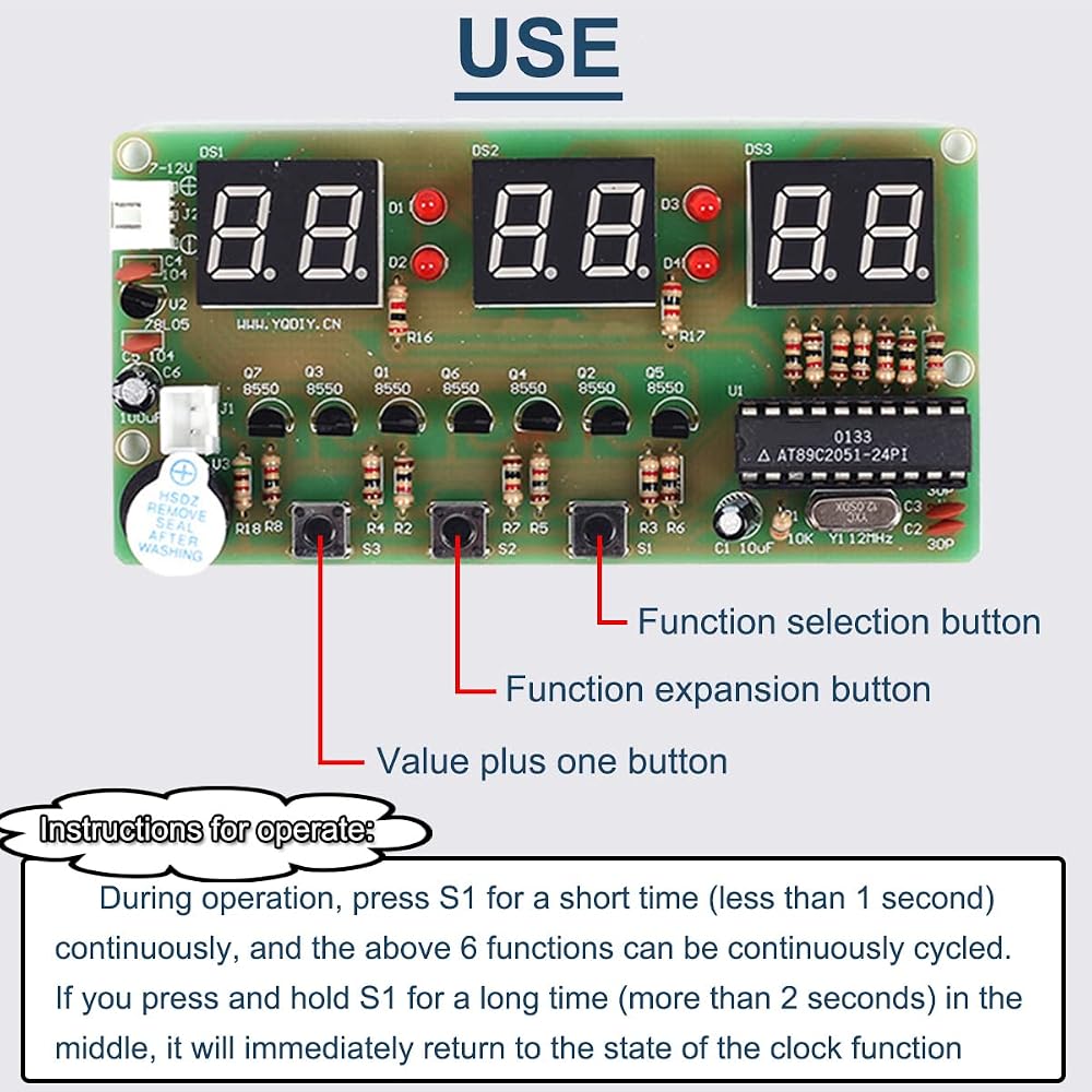
1. Function button description: The buttons are S1, S2, S3 from left to right, S1 is the function selection button, S2 is the function expansion button, and S3 is the value plus one button.
2. Operation instructions:
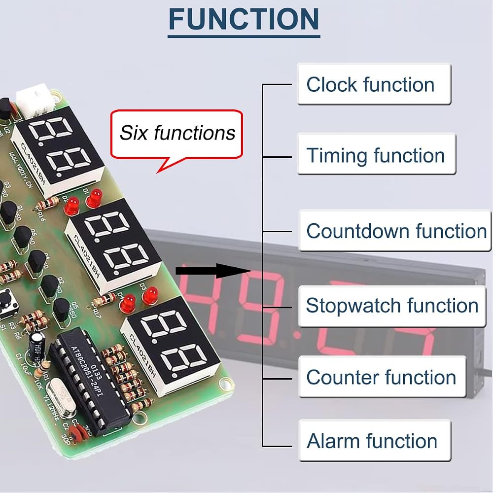
During operation, press S1 for a short time (less than 1 second) continuously to cycle through the above 6 functions. If you press and hold S1 for a long time (more than 2 seconds) in the middle, it will immediately return to the state of the clock function
Principle:
1. Display principle:
The main components of the display part are 3 two-digit common anode nixie tubes, driven by PNP type triodes, each port is equipped with a current limiting resistor, the driving mode is dynamic scanning, occupying P3.0~p3.5 ports, and the segment code is P1. 0~1.6 output. The colon part adopts four 3mm red light-emitting diodes, and the driving mode is the independent port P1.7 driving.
2. Keyboard principle:
The buttons S1~S3 are multiplexed with the P3.5, P3.4, and P3.2 ports of the display part.
Its working mode is that when the corresponding port outputs a high level, the state of the key is read and the jitter is eliminated by the single-chip microcomputer and the corresponding key value is given.
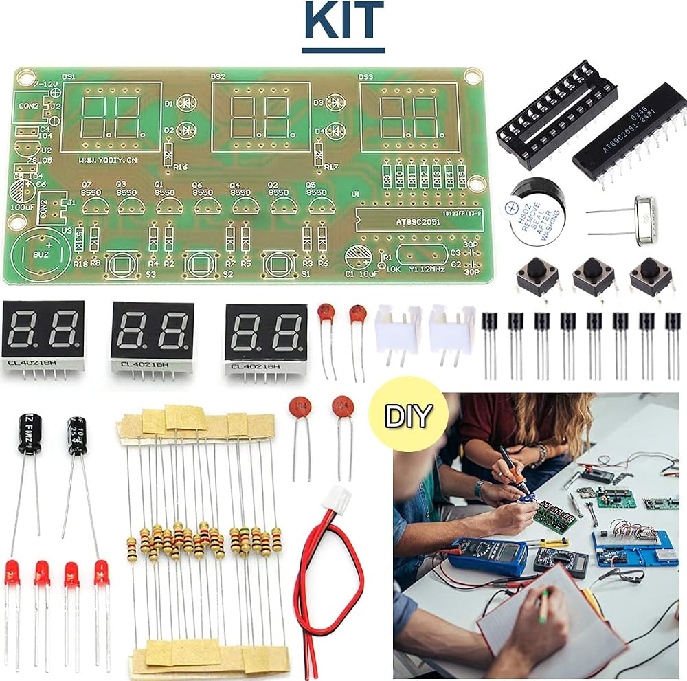
Package includes:
1 x 6 Bits Digital Electronic Clock DIY Kits
1 x 9V Battery Holder
1 x 9V Battery Clip
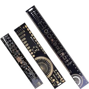 3PCS PCB Ruler 3Sizes 15/20/25cm 5.9/7.8/9.8in Multifunctional Engineering Ruler Resistor Capacitor Chip IC Measuring Tool Printed Circuit Board Ruler
SAR 45
3PCS PCB Ruler 3Sizes 15/20/25cm 5.9/7.8/9.8in Multifunctional Engineering Ruler Resistor Capacitor Chip IC Measuring Tool Printed Circuit Board Ruler
SAR 45
 -10%
10PCS IIC I2C Logic Level Converter 4 Channels Bi-Directional Level Voltage Module 3.3-5V Shifter for Arduino, with Dupont Cable
SAR 37
-10%
10PCS IIC I2C Logic Level Converter 4 Channels Bi-Directional Level Voltage Module 3.3-5V Shifter for Arduino, with Dupont Cable
SAR 37
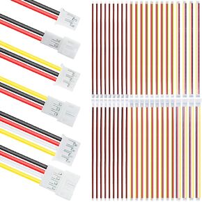 JST PH 2.0 Micro Electrical Male and Female Plug Connector 2/3/4 Pin Connection Plug Spacing 2.0mm 26AWG 20cm Silicone Wire Cable(30 Pair) for LED Light
SAR 47
JST PH 2.0 Micro Electrical Male and Female Plug Connector 2/3/4 Pin Connection Plug Spacing 2.0mm 26AWG 20cm Silicone Wire Cable(30 Pair) for LED Light
SAR 47
 -6%
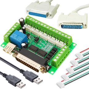
5 Axis CNC Stepper Motor Interface Board Breakout Board Mach3 Interface Board Optical Coupler Board with XH2.54 4P Cable Double USB Cable DB25 Male to Female Cable
SAR 83
-6%
5 Axis CNC Stepper Motor Interface Board Breakout Board Mach3 Interface Board Optical Coupler Board with XH2.54 4P Cable Double USB Cable DB25 Male to Female Cable
SAR 83