- Shopping, made easy.
- /
- Get the app!
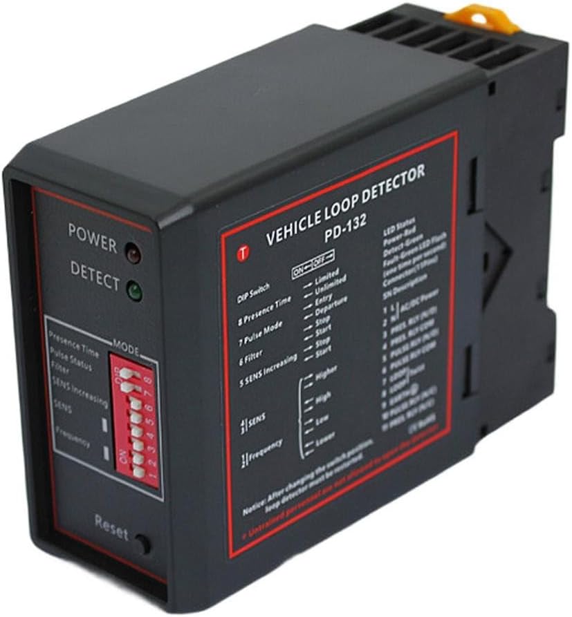
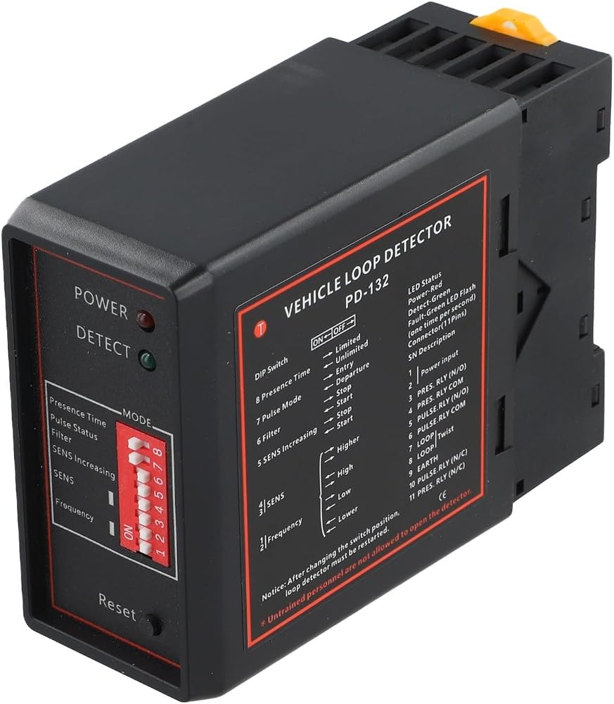
Features:
The detector should be mounted in a convenient, weatherproof location as close to the circuit as possible.
The mounting location should be away from heat sources; at least 10 mm should be maintained from other equipment (it should not be mounted close to the wall of the junction box).
Proper loop configuration and detector mounting will for ensure successful operation of the inductive loop detection system.
Several important parameters of the loop include: loop shape, size, number of turns, and mounting way.
Operation and Indications
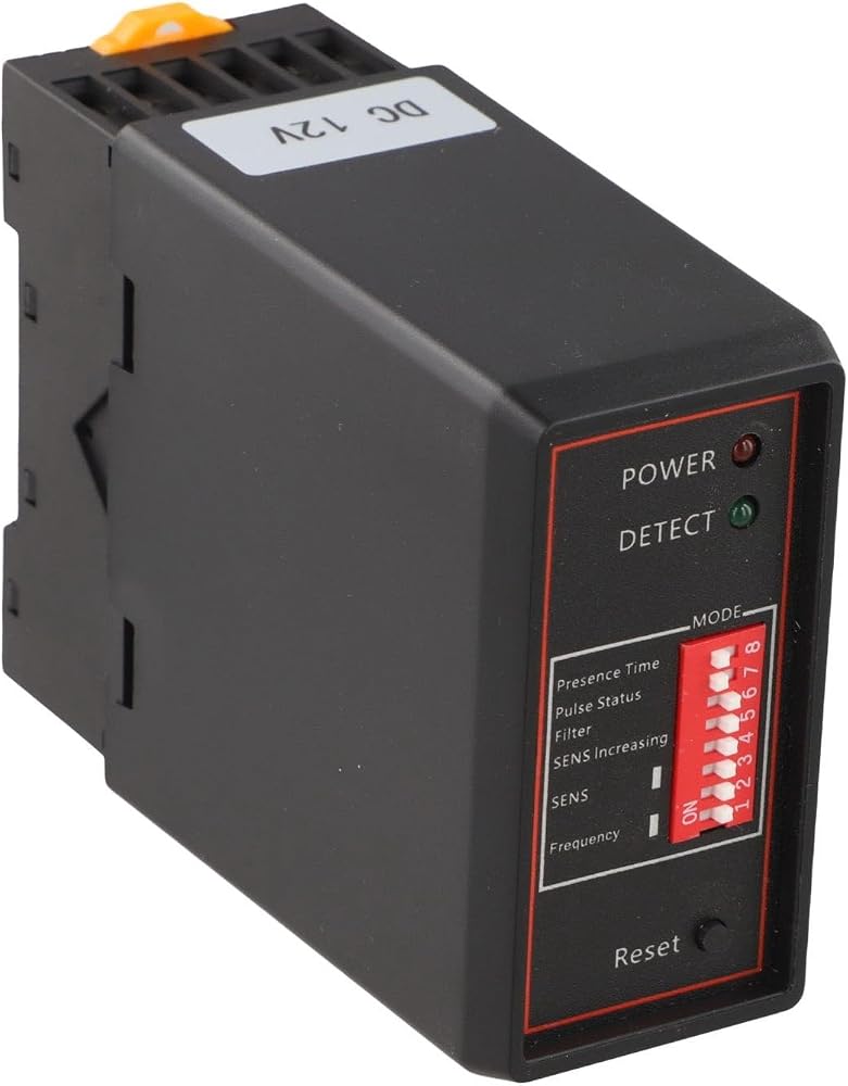
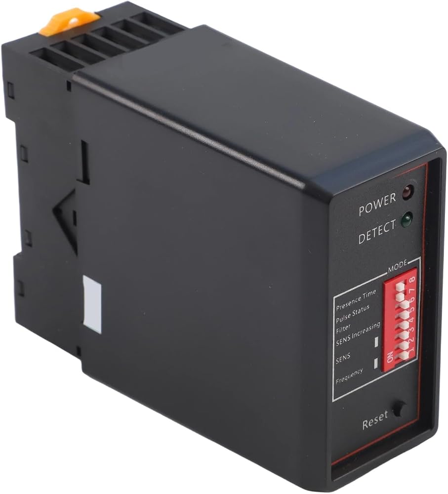
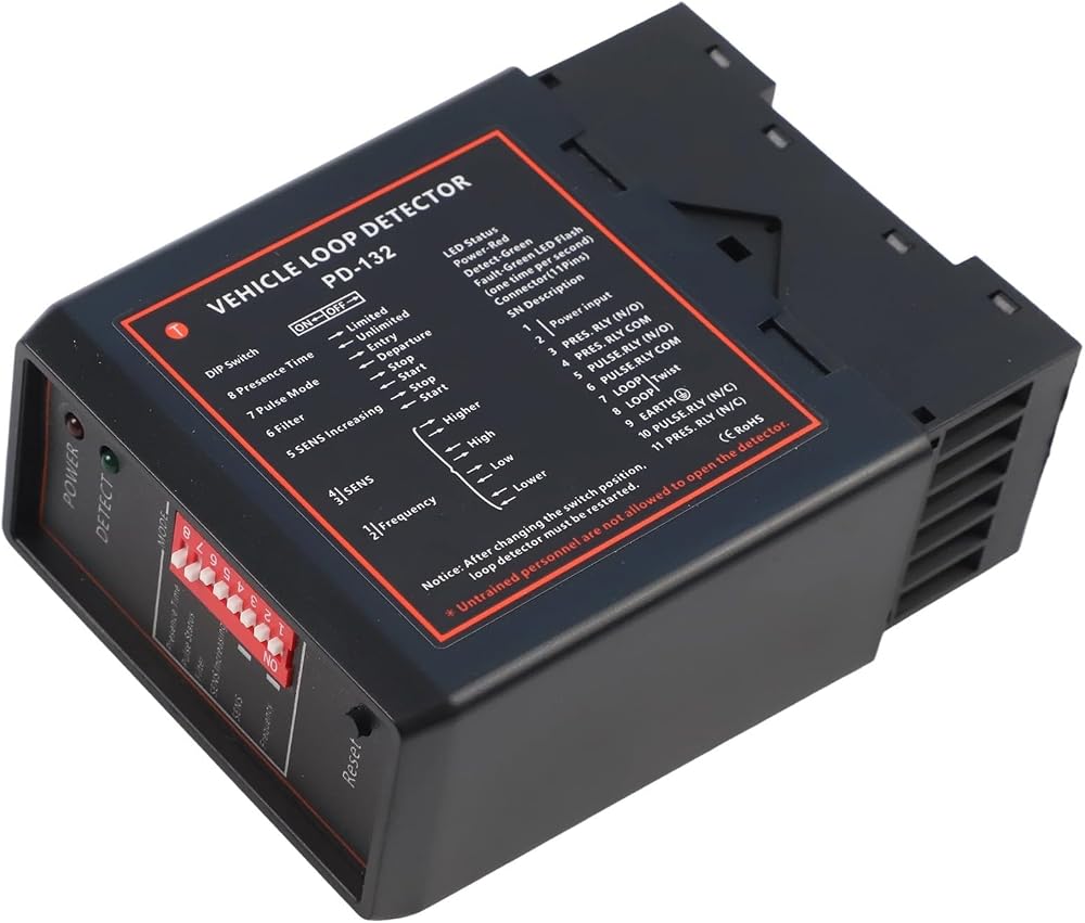
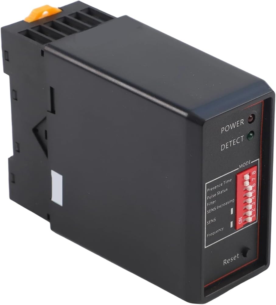
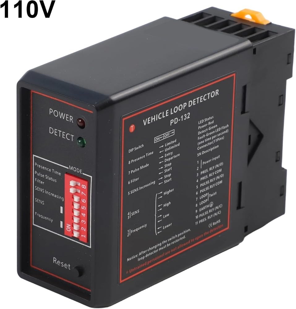
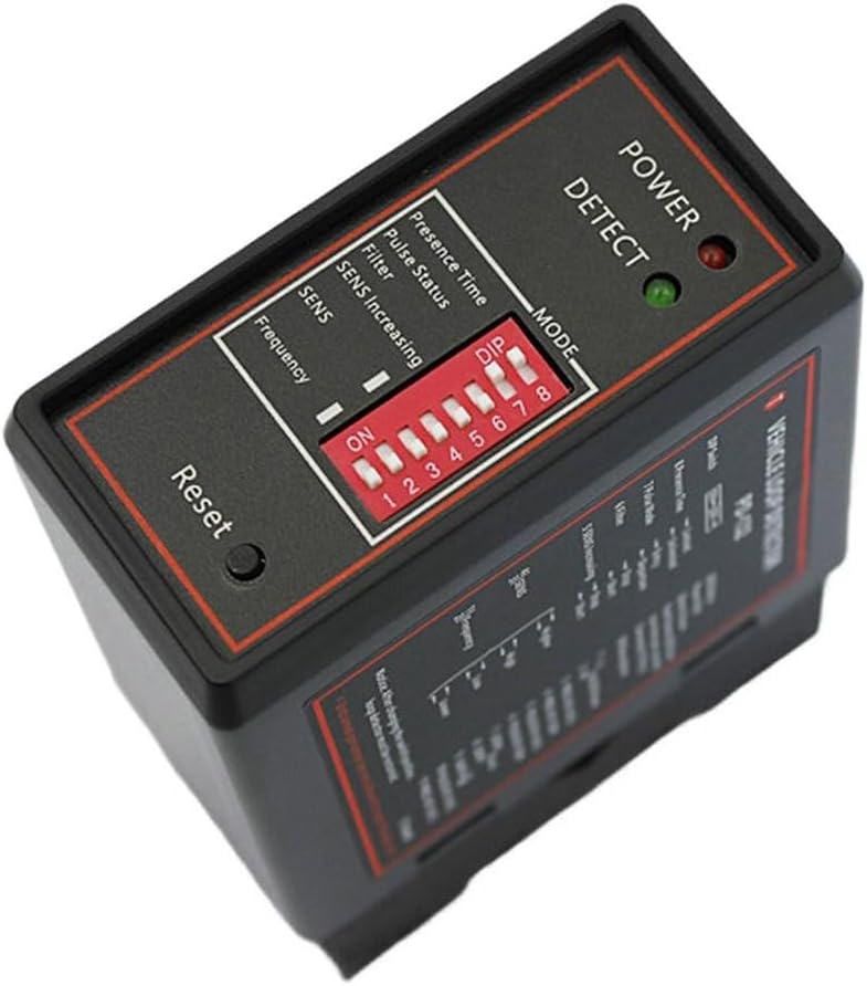
During the tuning of the detector, both the green LED and the power LED will illuminate. They will remain on for approximately 2 seconds, then the green LED will turn off. If a fault occurs in the loop, LED will illuminate and flash to indicate the fault.
If the fault has self-corrected, the detector will continue to operate. The green LED will also illuminate whenever a vehicle is detected passing through the inductive loop.
The power LED on the top of the device will remain on to indicate that the device is powered.
Specification:
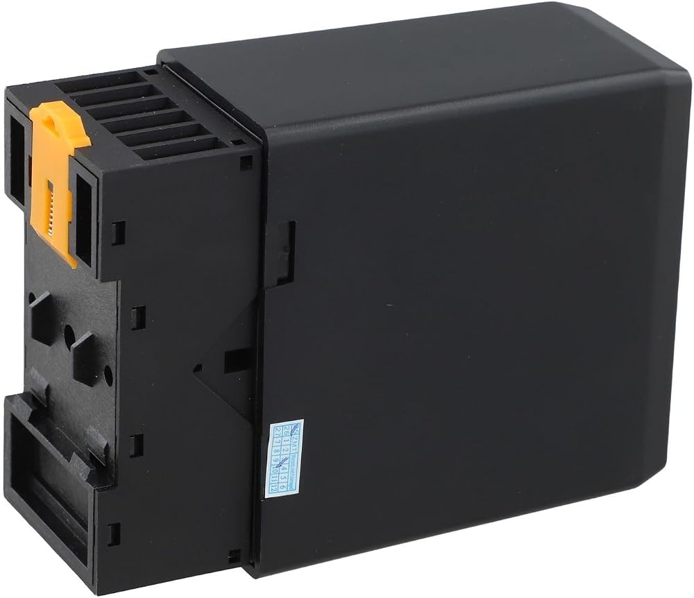
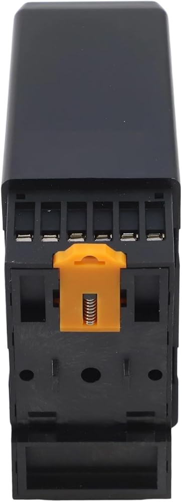
Part Name: Inductive Loop Detector
Material: ABS
Color: Black
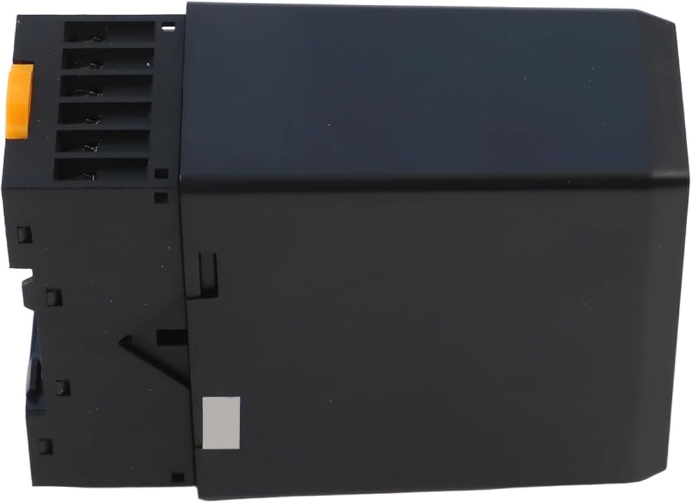
size: 78x40x108 mm (L x W x H)
Supply Voltage: 230 for VAC, 115 for VAC, 24 VDC/AC, 12 VDC/AC (see label on detector)
AC Voltage Tolerance: +10% / -15%
DC Voltage Tolerance: ±15%
Power Consumption: 4.5 VA
Output Relay: 240V/5A
Operating Temperature: -20°C to +65°C
Storage Temperature: -40°C to +85°C
for frequency Range: 20 kHz to 170 kHz
Reaction Time: 10 for ms
Signal Hold Time: Infinite / Limited to 10 minutes when loop is permanently covered
Sensitivity: 4 levels adjustable
Loop Inductance: Total loop plus connecting wires: 50 μH to 1000 μH.
for Ideal value is 100 μH to 300 μH
Loop connection wiring: Maximum length 20 meters, at least 20 times per meter
Package content:
1*Inductive loop detector
 Microscope LED Ring Light Energy Saving High Brightness Flickerless Low Heat Long Lifespan ABS Plastic Black USB Cable Included For Biological Microscopes Stereo Monocular Video Optical Instruments(B)
SAR 74
Microscope LED Ring Light Energy Saving High Brightness Flickerless Low Heat Long Lifespan ABS Plastic Black USB Cable Included For Biological Microscopes Stereo Monocular Video Optical Instruments(B)
SAR 74
 Differential Housing Axle Vent J5352955 Plastic Material Direct Replacement 1993-2014 Vehicle Fitment
SAR 47
Differential Housing Axle Vent J5352955 Plastic Material Direct Replacement 1993-2014 Vehicle Fitment
SAR 47
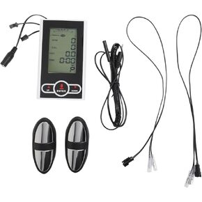 Exercise Bike Monitor Speedometer for Stationary Bike or Elliptical Trainer, Plastic Replacement Display with Heart Rate, Time, Speed, Calories, Mileage and Scan Functions
SAR 89
Exercise Bike Monitor Speedometer for Stationary Bike or Elliptical Trainer, Plastic Replacement Display with Heart Rate, Time, Speed, Calories, Mileage and Scan Functions
SAR 89
 For MKS DLC32 V2.1 Engraver Control Board - Offline Carving, Dual Core 32-Bit 240MHz, WiFi & BT, For Engraving Machines CNC Carving Equipment
SAR 102
For MKS DLC32 V2.1 Engraver Control Board - Offline Carving, Dual Core 32-Bit 240MHz, WiFi & BT, For Engraving Machines CNC Carving Equipment
SAR 102