- Shopping, made easy.
- /
- Get the app!
1. Key Parameters
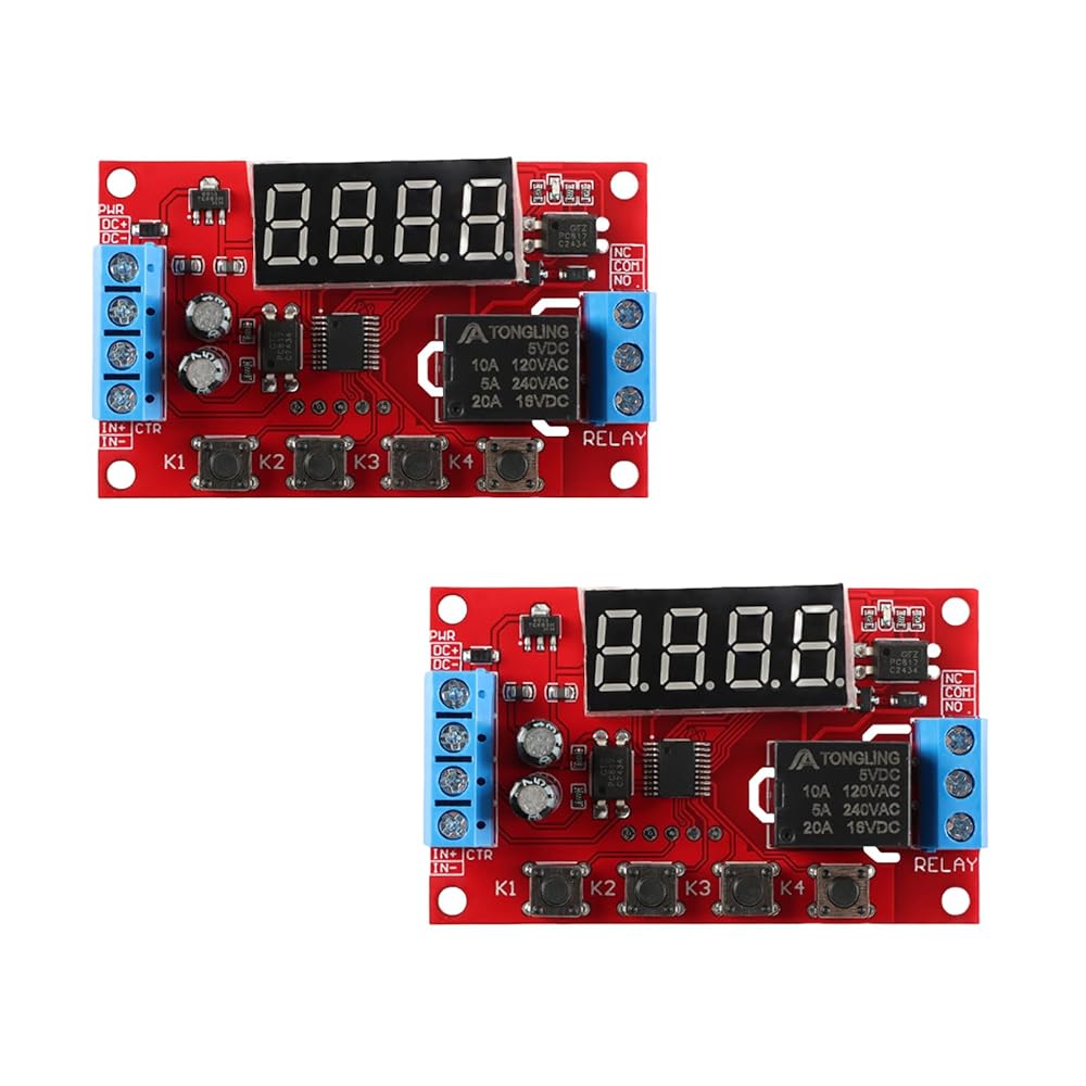
Input Voltage: 5V DC ±0.5V (Stable Regulated Supply Required)
Output Load:
DC Load: 10A Max @30V DC
AC Load: 5A Max @250V AC
Control Logic: 32 Preset Functions (Microcontroller-Based)
Trigger Signal: High Level (5V TTL Compatible)
Power Consumption: Static 20mA; Operating 60mA
Time Range: 0.01s–999min (Adjustable via Decimal Point)
Temperature Range: -25°C to +85°C (Reliable)
Memory Function: Power-Off Settings Retention
Dimensions: 65mm × 34.3mm × 17.5mm (DIN/PCB Mount)
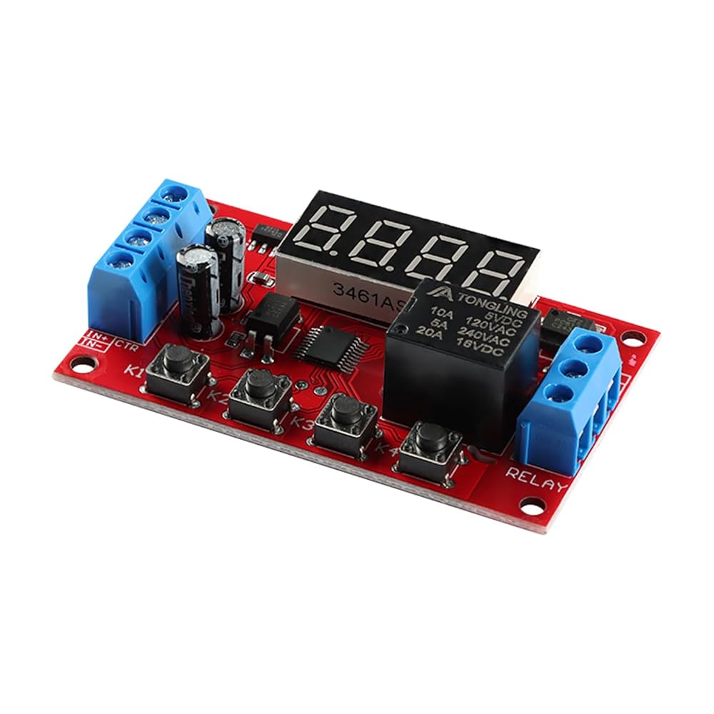
2. Pin Functions
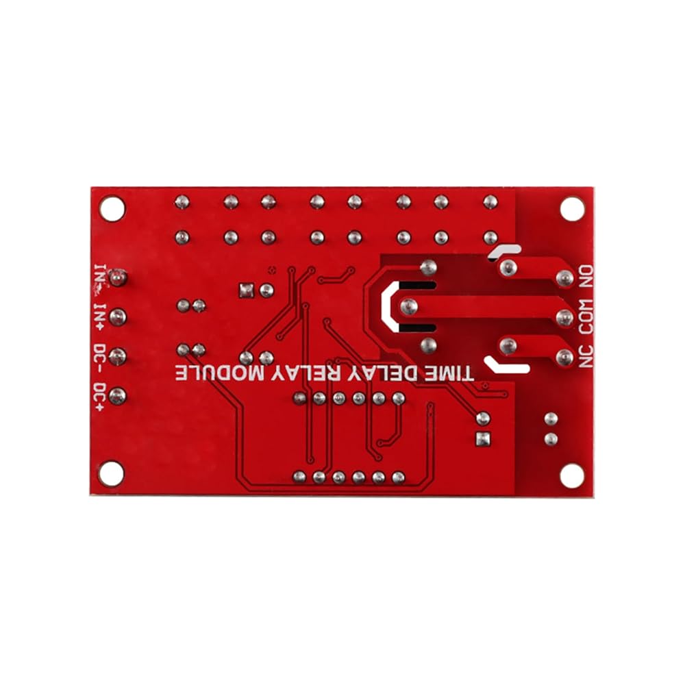
DC+: 5V Power Input - Connect to regulated 5V source
DC-: Power Ground - Common reference for all circuits.
IN+: Signal Input Positive - Accepts 5V high-level trigger (e.g., MCU/switch).
IN-: Signal Input Negative - Tie to GND if using single-wire trigger.
COM: Relay Common Terminal - Central contact for NO/NC switching.
NO: Normally Open Contact - Connects to COM when relay activated.
NC: Normally Closed Contact - Disconnects from COM when relay activated.
3. Frequently Asked Questions (FAQ)
Q1: Relay does not trigger despite correct power?
A:
Verify IN+ receives ≥3.5V signal; ensure DC- is grounded .
Add flyback diode across COM-NO for DC loads (e.g., 1N4007) .
Q2: How to set cycle modes (e.g., A→B→repeat)?
A:
Hold K1 for 2s → Select mode (e.g., P-44 for loop) → Short-press K1 → Set time A/B/C → K4 sets decimal (e.g., A=10.0s) .
Q3: LCD shows "Err" after power cycle?
A: Re-calibrate timing: Reset A/B/C values via K1-K4 keys; default mode = P-0 (single trigger) .

 -40%
MAX6675 Type K Thermocouple Temperature Sensor Module for Arduino, Accurate Temperature Measurement 3.0-5.5V
SAR 32
-40%
MAX6675 Type K Thermocouple Temperature Sensor Module for Arduino, Accurate Temperature Measurement 3.0-5.5V
SAR 32
 SPH0645LM4H I2S MEMS Microphone Breakout Board for Arduino Raspberry Pi, 1.6-3.6V Digital Sound Sensor for DIY Audio Projects
SAR 53
SPH0645LM4H I2S MEMS Microphone Breakout Board for Arduino Raspberry Pi, 1.6-3.6V Digital Sound Sensor for DIY Audio Projects
SAR 53
 10Pcs B50K Potentiometer RK097G 50K Dual Speaker Amplifier 15mm 6Pin Sealed Potentiometer
SAR 32
10Pcs B50K Potentiometer RK097G 50K Dual Speaker Amplifier 15mm 6Pin Sealed Potentiometer
SAR 32
 3Pcs 4S Lithium-ion Battery Charger Board Li-Ion USB-C DC 3-6V to 16.8V Charger Module Board 4A 18650 Lithium Boost Module USB Type-C Protection Board
SAR 42
3Pcs 4S Lithium-ion Battery Charger Board Li-Ion USB-C DC 3-6V to 16.8V Charger Module Board 4A 18650 Lithium Boost Module USB Type-C Protection Board
SAR 42