- Shopping, made easy.
- /
- Get the app!
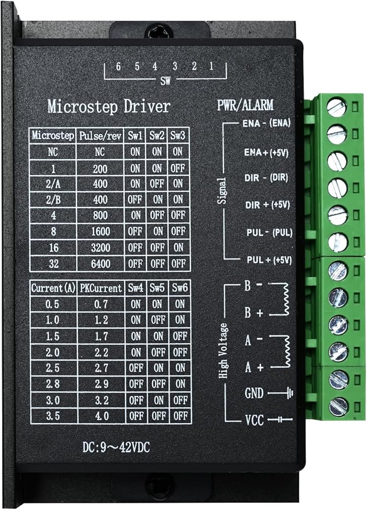


This driver is an updated version based on the TB6600 architecture, with microstepping resolution increased to 32 subdivision, making it suitable for high-subdivision applications.
Compatible with stepper motors: 42, 57, and 86 frame sizes in two-phase and four-phase configurations (4-wire, 6-wire, 8-wire).
DC power supply voltage: 9V–40V
H-bridge bipolar constant current drive
Eight selectable output current settings, up to a maximum of 4.0A
Six selectable microstepping modes, up to a maximum of 32 subdivision
Input signals feature high-speed optocoupler isolation
Standard common-anode single-pulse interface
Enable (EN) control for motor disengagement – allows manual shaft rotation when active
Semi-enclosed housing for reliable operation in more demanding environments
Energy-saving semi-automatic current reduction during standstill
Built-in over-temperature protection and over-current protection
Weight: 201g
Terminal Block Definitions
Signal Input Terminals
(1) CP+: Pulse input positive
(2) CP-: Pulse input negative
(3) DIR+: Direction control positive (forward/reverse)
(4) DIR-: Direction control negative
(5) EN+: Enable (disengage) control positive
(6) EN-: Enable (disengage) control negative
Motor Winding Connections
(1) A+: Connect to motor winding A+
(2) A-: Connect to motor winding A-
(3) B+: Connect to motor winding B+
(4) B-: Connect to motor winding B-
Power Supply Connections
(1) VCC: DC power positive (Note: 10V
(2) GND: DC power negative
Optocoupler Input Wiring Options
The input interface supports two wiring configurations:
1. Common-Anode Connection
Connect CP+, DIR+, and EN+ to the control system's logic power supply.
If the logic supply is +5V, connect directly.
If the logic supply exceeds +5V, add an external current-limiting resistor R to ensure 8–15mA of drive current through the internal optocouplers.
Pulse signals are applied to CP-. In this configuration, DIR- and EN- are active-low.
2. Common-Cathode Connection
Connect CP-, DIR-, and EN- to the control system's signal ground (SGND, isolated from power ground).
Apply pulse signals to CP+. In this configuration, DIR+ and EN+ are active-high.
The value and placement of the current-limiting resistor R are identical to those in the common-anode method.
Note: The EN terminal may be left unconnected. When the EN signal is active, the motor is disengaged (rotor free to rotate), allowing manual adjustment of the shaft position. After adjustment, deactivate EN to resume automatic control.
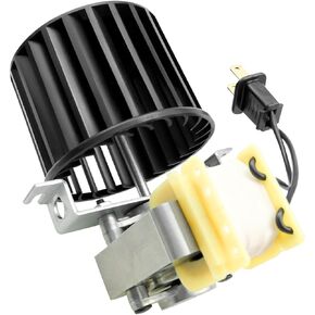 S97009796 Fan Blower Motor Assembly for Broan Bulb Heater Bathroom 162 and 164 E, G, J, K, L, M Replace 97009796 S97009796B 99080351
SAR 125
S97009796 Fan Blower Motor Assembly for Broan Bulb Heater Bathroom 162 and 164 E, G, J, K, L, M Replace 97009796 S97009796B 99080351
SAR 125
 BEMONOC DC 12V 0.6RPM 6mm Shaft Low Speed High Torque Turbine Worm Gear Motor
SAR 84
BEMONOC DC 12V 0.6RPM 6mm Shaft Low Speed High Torque Turbine Worm Gear Motor
SAR 84
 ClimaTek Upgraded 1/6 HP Condenser Fan Motor Replaces Trane American Standard #s MOT18687 MOT12919 MOT10478
SAR 1,377
ClimaTek Upgraded 1/6 HP Condenser Fan Motor Replaces Trane American Standard #s MOT18687 MOT12919 MOT10478
SAR 1,377
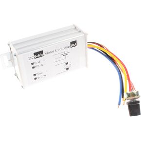 NOYITO PWM Motor Speed Controller 10A DC 9V-60V 12V 24V 36V 48V Motor Controller Third gear Forward Reverse Stop (10A Third-gear)
SAR 43
NOYITO PWM Motor Speed Controller 10A DC 9V-60V 12V 24V 36V 48V Motor Controller Third gear Forward Reverse Stop (10A Third-gear)
SAR 43