- Shopping, made easy.
- /
- Get the app!
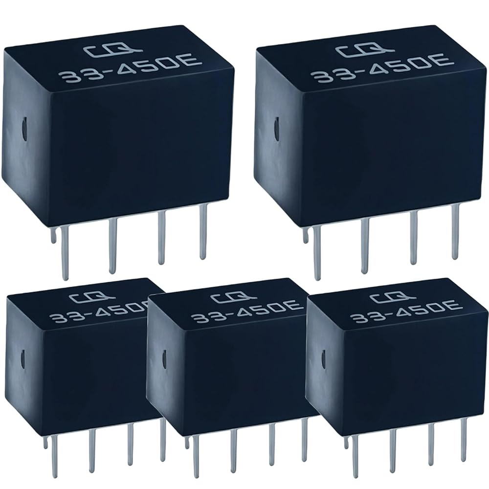
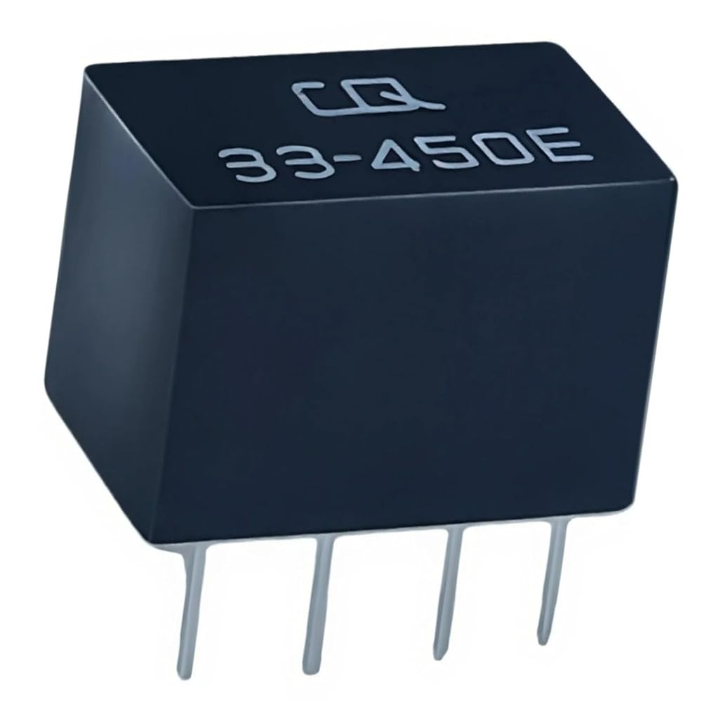
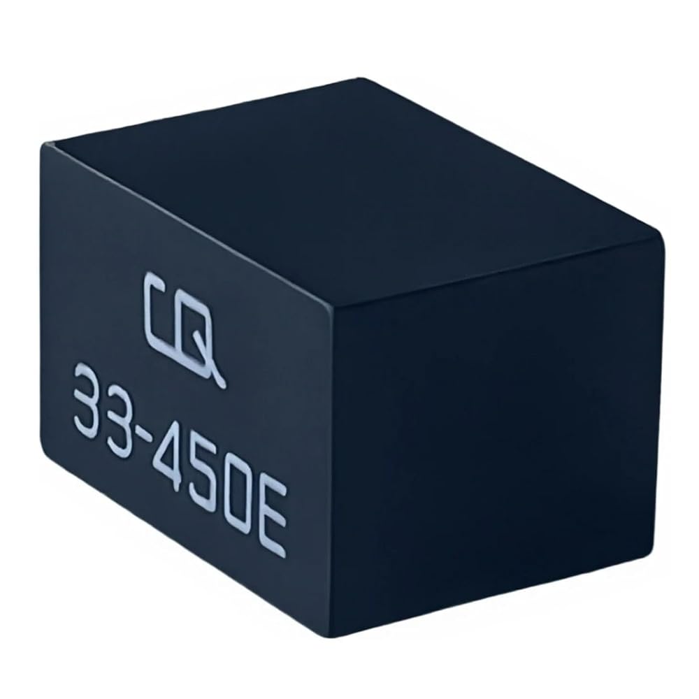
LT450EW 450 kHz IF Ceramic Filter (4+1 pins)
Function: 5-element ceramic ladder filter for 450 kHz intermediate-frequency stages in communications receivers and transceivers.
Electrical: Center freq. 450 ±1.5 kHz; 6 dB bandwidth ±7.5 kHz (15 kHz total); wide-band “E” grade for FM(W)/wide IF paths.
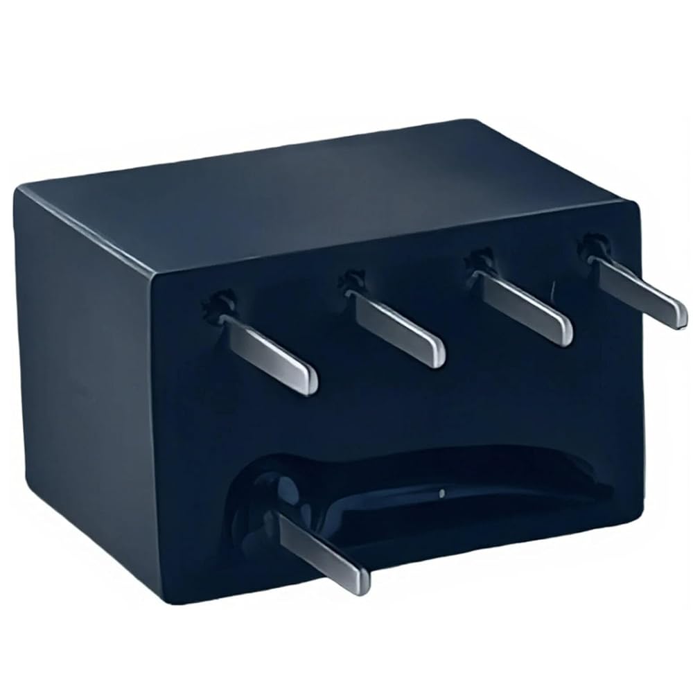
Package: Through-hole DIP, 5 pins in a 4+1 keyed layout; body approx. 11.0 × 7.0 × 8.0 mm.
Typical Use: IF filtering to improve selectivity and adjacent-channel rejection when refurbishing or repairing radio equipment.
Cross-Reference (for search/use verification): LT450EW, LT450E, CF 450EW, CFWS450E. Always match frequency, bandwidth, and pin layout to your PCB footprint.
Install Notes: Desolder the original filter with ESD-safe technique; align the single key pin; solder cleanly and remove flux; verify the IF alignment per service manual.
In the Box: 1 × LT450EW 450 kHz ceramic IF filter (4+1 pins).
Compatibility reminder: This component fits equipment that specifies a 450 kHz IF filter with a 4+1 pin footprint. It is not an automotive relay or vehicle-specific part.
 90987-04010/156700-2550 12V 5-Pin Relay — HVAC Blower/Defogger — Replaces 90080-87025 — Compatible with Toyota-Camry/Corolla/Highlander
SAR 37
90987-04010/156700-2550 12V 5-Pin Relay — HVAC Blower/Defogger — Replaces 90080-87025 — Compatible with Toyota-Camry/Corolla/Highlander
SAR 37
 -11%
4 Pin Relay 25230-79917 for Nissan Titan Versa Xterra Infiniti, 2004-2015; Pathfinder, 2013-2020; Blue, 12V DC, 30A, Normally Open, Panel Mount, Automatic Operation (4)
SAR 47
-11%
4 Pin Relay 25230-79917 for Nissan Titan Versa Xterra Infiniti, 2004-2015; Pathfinder, 2013-2020; Blue, 12V DC, 30A, Normally Open, Panel Mount, Automatic Operation (4)
SAR 47
 3PCS 12193604 Relay - 30A 12VDC 4-Pin SPST Automotive Relay - Compatible with GM Vehicles (for Chevrolet Silverado, Buick Enclave) for AC Failures & Start System Issues,Replace 0545620B VF28-11F14-Z05
SAR 68
3PCS 12193604 Relay - 30A 12VDC 4-Pin SPST Automotive Relay - Compatible with GM Vehicles (for Chevrolet Silverado, Buick Enclave) for AC Failures & Start System Issues,Replace 0545620B VF28-11F14-Z05
SAR 68
 4-Pack 0025422319 5-Pin Green Relay, Compatible with Mercedes-Benz ML/GL (W164/X164) & S-Class (W221) — Replaces 0009828523, 0025427619, 4RA 007 791-52 — 12V Multi-Purpose/Air-Suspension/Starter
SAR 67
4-Pack 0025422319 5-Pin Green Relay, Compatible with Mercedes-Benz ML/GL (W164/X164) & S-Class (W221) — Replaces 0009828523, 0025427619, 4RA 007 791-52 — 12V Multi-Purpose/Air-Suspension/Starter
SAR 67