- Shopping, made easy.
- /
- Get the app!
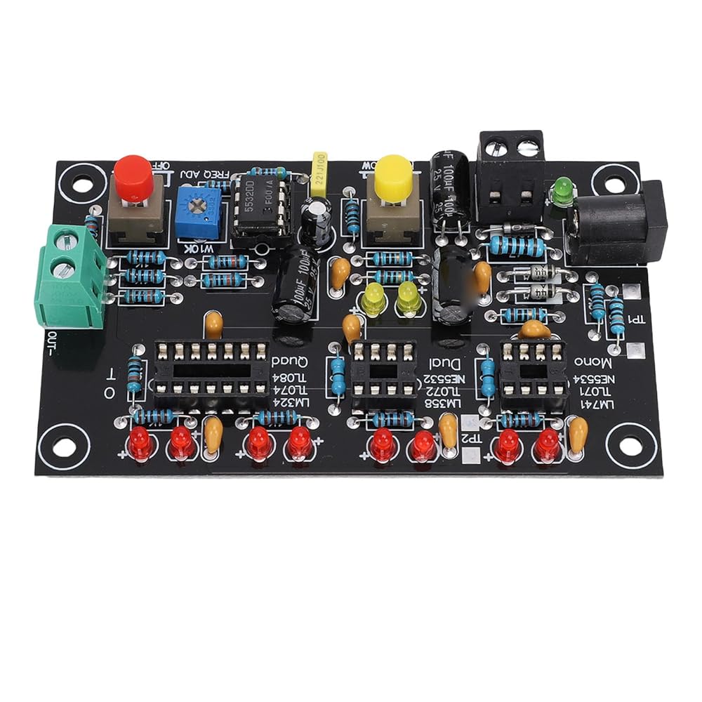
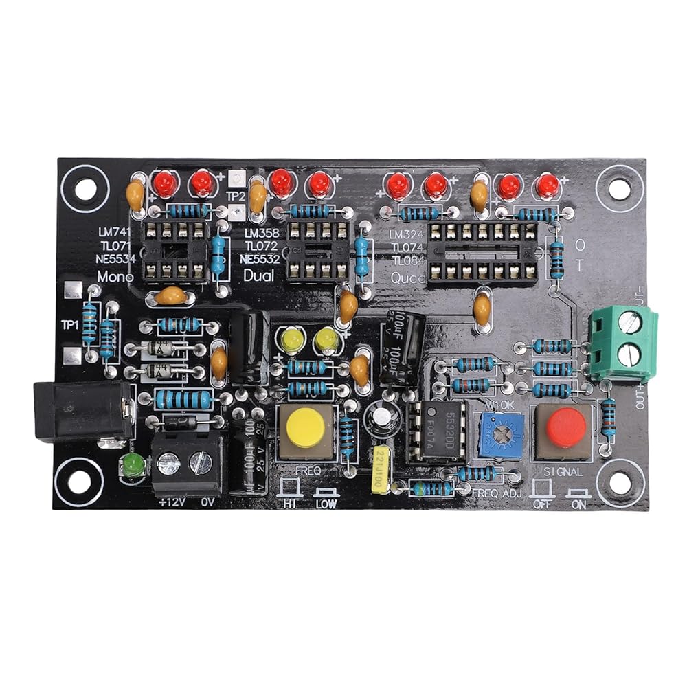
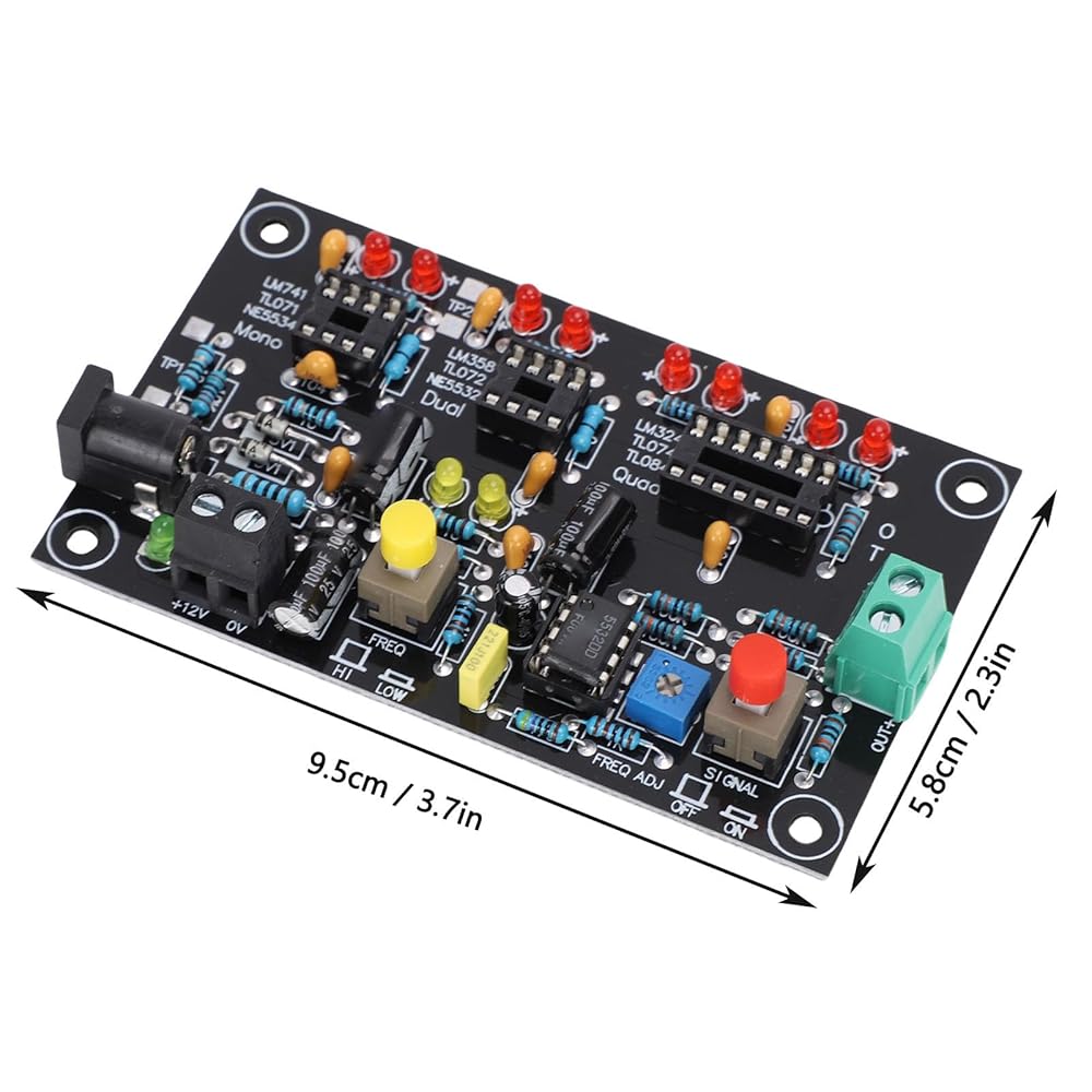
Specification:
Item Type: Operational Amplifier Testing Module Board
Material: PCB
Size: Approx. 9.5x5.8cm / 3.74x2.28in
Power Supply Requirements(2 modes, you can choose one of them according to the actual situation):
1. Wiring Method: Current: Above 100mA
2. Use A Regular Monitoring Power Supply: 1A power adapter, plug approx. 5.5 x 2.5mm / 0.22 x 0.1in
, positive inside and negative outside.
Application:
For Single OP AMP Model: LM741, LF356, NE5534, TL071, TL081, 0P07 and other standard single OP AMP packages
For Double OP AMP Model: LM358, NE5532, TL072, TL082, MC1458, RC4558, 0P275, AD827 and other standard double OP AMP packages
For Quad OP AMP Model: LM324, TL074, TL084, LF347, AD713
How to Use:
Direct installation and use
Package List:
1 x Operational Amplifier Testing Module Board
Notice:
Testing Instructions:1. Only test one chip at a time. Use one of the three test sockets.
2. For static current testing, use the DC voltage meter of the digital multimeter. Test the voltage across 10 ohms, 1=V/10 (ma). For example, V=15MV, static current 1=1.5 ma. (at this time, do not press the red switch on the right side of the diagram).
3. The test end can be connected to an oscilloscope or frequency counter. Adjust the potentiometer to change the test frequency.
 10 Speed Bike Groupset 42T Flywheel Bike Shift Kit Crank Shifter Rear Derailleur Chain Set
SAR 509
10 Speed Bike Groupset 42T Flywheel Bike Shift Kit Crank Shifter Rear Derailleur Chain Set
SAR 509
 Electric Scooter Brake Caliper Aluminum Alloy Strong Power Electric Scooter Replacement Parts for GOTRAX Black
SAR 112
Electric Scooter Brake Caliper Aluminum Alloy Strong Power Electric Scooter Replacement Parts for GOTRAX Black
SAR 112
 6Pcs Gold Metal Bullet Buttons & Thumbstick Mod Kit for PS4 Controller
SAR 87
6Pcs Gold Metal Bullet Buttons & Thumbstick Mod Kit for PS4 Controller
SAR 87
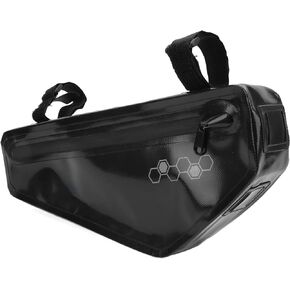 Bicycle Triangle Frame Bag Large Capacity Waterproof Mountain Bike Pouch for Outdoor Sports
SAR 55
Bicycle Triangle Frame Bag Large Capacity Waterproof Mountain Bike Pouch for Outdoor Sports
SAR 55