- Shopping, made easy.
- /
- Get the app!
Product Parameters Parameters
Operating Voltage: 3.3V–5.0V DC
Absolute Angle Resolution: 15 Bits (32,768 Steps/Circle via SPI)
Incremental Output:
ABZ: 1–4,096 Pulses/Cycle (Programmable)
UVW: 1–16 Pole Pairs (Programmable)
PWM Output: 12-Bit Absolute Angle (Single-Wire Transmission)
Accuracy: INL ≤ ±0.07° (After Calibration)
Response Delay: 2–10 μs (Supports 120,000 RPM)
Operating Temperature: –40°C to +125°C (Reliable)
Communication: 4-Wire SPI (Standard/Fast Mode)
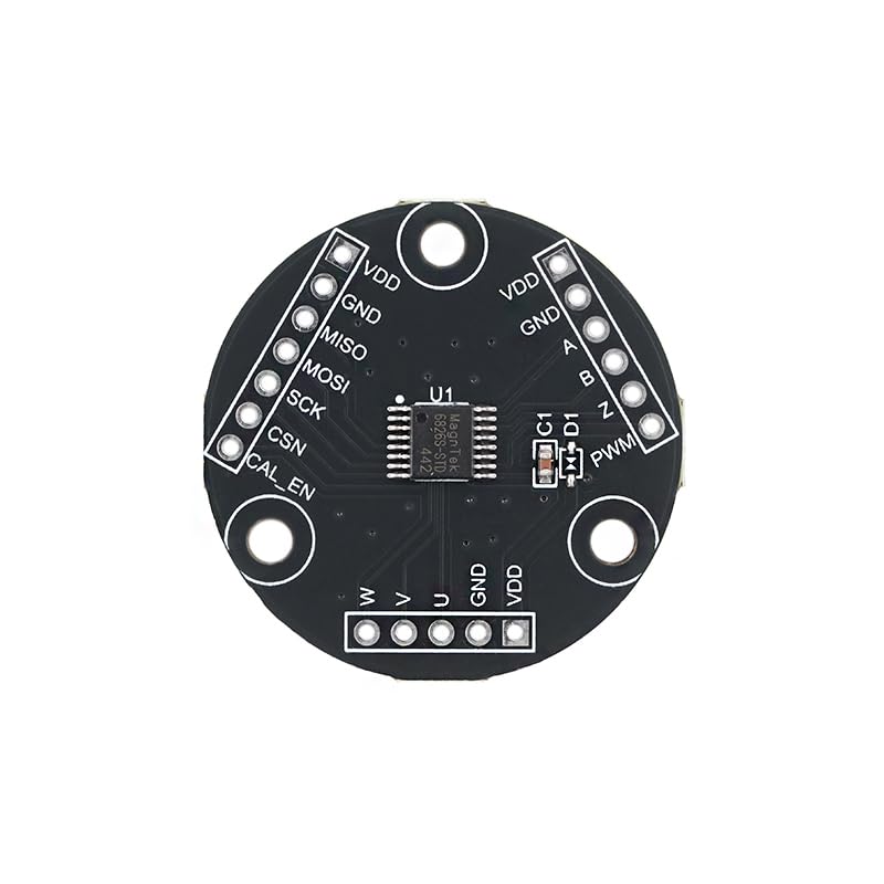
Pin Functions ( )
VDD: Power Input (3.3V–5.0V). Decouple with 0.1μF Ceramic + 10μF Electrolytic Capacitor.
GND: System Ground. Share with Controller and Magnet Bracket (PCB Copper ≥90%).
SCLK: SPI Clock Input. Requires 4.7kΩ Pull-Up to VDD (Trace Length ≤20 cm).
SDI: SPI Data Input (Host to Slave). Use Twisted Pair for Noise Immunity.
SDO: SPI Data Output (Slave to Host). Connect to MCU MISO Pin.
CS: SPI Chip Select (Active Low). Independent Control for Multi-Module Cascading.
PWM: 12-Bit Absolute Angle Output (Duty Cycle = Angle/360°).
ABZ: Incremental Quadrature Output (A/B Phase 90° Difference, Z Index Pulse).
UVW: Motor Commutation Signal (U/V/W Phase 120° Difference).
FAQ
1.
Fixed Angle Deviation (e.g., Constant 5° Offset)?
→ Perform Self-Calibration: Power On and Keep Module Still for 2 Seconds (LED Stops Flashing When Complete). Ensure Magnet S-Pole Faces Module Marking Surface.
2.
SPI Communication Unresponsive?
→ Check CS Pin Independence for Multi-Module setups (Default Address 0x40). Add 4.7kΩ Pull-Up Resistors to SCLK/SDI/SDO Lines.

 2Pcs 2.4 Inches TFT LCD Screen Module 2.4Inch 320x240 SPI Serial ILI9341 SPI 2.4" Screen Shield Display Module Development Board
SAR 89
2Pcs 2.4 Inches TFT LCD Screen Module 2.4Inch 320x240 SPI Serial ILI9341 SPI 2.4" Screen Shield Display Module Development Board
SAR 89
 10Pcs IRF520 MOSFET Driver Module MOS Field-Effect Transistor Driver Module Triode for Arduino MCU ARM Raspberry PI
SAR 47
10Pcs IRF520 MOSFET Driver Module MOS Field-Effect Transistor Driver Module Triode for Arduino MCU ARM Raspberry PI
SAR 47
 4Pcs 10K Dual Channel Analog Potentiometer Module Slide Potentiometer Log Slide Pot Potentiometer Module for Arduino AVR Electronic Block Electronic Building Block Sliding Adjustable Resistor
SAR 53
4Pcs 10K Dual Channel Analog Potentiometer Module Slide Potentiometer Log Slide Pot Potentiometer Module for Arduino AVR Electronic Block Electronic Building Block Sliding Adjustable Resistor
SAR 53
 10Pcs B50K Potentiometer RK097G 50K Dual Speaker Amplifier 15mm 6Pin Sealed Potentiometer
SAR 32
10Pcs B50K Potentiometer RK097G 50K Dual Speaker Amplifier 15mm 6Pin Sealed Potentiometer
SAR 32