- Shopping, made easy.
- /
- Get the app!
1. Product Parameters
Input Voltage: 3.3V–5V DC (Internal LDO Regulator)
Sensors:
Gyroscope: ±250/500/1000/2000°/s (Programmable)
Accelerometer: ±2/4/8/16g (16-bit ADC)
Magnetometer: ±4800μT (AK8963 Chip)
Communication: I²C (400kHz) / SPI (1MHz)
Output Data: 9-axis fused motion tracking (DMP Support)
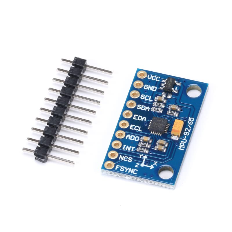
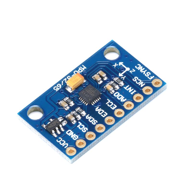
Dimensions: 25×15mm (2.54mm Pin Spacing)
2. Key Pin Functions
Power & Control
VCC: 3.3V–5V DC Input (Stable power critical – add 0.1μF decoupling capacitor)
GND: Power/Signal Ground (Single-point grounding to reduce noise)
SDA: I²C Data Line / SPI MOSI (Requires 4.7kΩ pull-up resistor)
SCL: I²C Clock Line / SPI SCK
Optional Pins
INT: Interrupt Output (e.g., motion detection)
AD0: I²C Address Select (Low: 0x68; High: 0x69)
⚠️ SPI Mode: Connect NCSto MCU GPIO for chip select .
3. Common Issues & Solutions
Q1: I²C/SPI Communication Failure?
Fix 1: Verify pull-up resistors on SDA/SCL (4.7kΩ to VCC) .
Fix 2: Check address conflict (Default I²C: 0x68) .
Q2: Magnetic Data Drift (>±5%)?
Calibration: Place module in figure-8 motion for 30 sec (hard-iron calibration) .
Shielding: Keep >5cm from motors/transformers .
Q3: DMP Initialization Error?
Fix: Update firmware/library (e.g., MPU9250_asukiaaav1.5.10+) .
Q4: High Gyro Noise?
Filter: Set digital LPF to 5Hz (DLPF_CFG=0x06) .

 3Pcs USB to TTL UART CH340G Serial Adapter, 3.3V/5V Switchable for Microcontroller Programming, Compatible with STC Brush Board Modules
SAR 47
3Pcs USB to TTL UART CH340G Serial Adapter, 3.3V/5V Switchable for Microcontroller Programming, Compatible with STC Brush Board Modules
SAR 47
 10 Sets RT Split Ultrasonic Transceiver Sensor Probe 10 Transmitters + 10 Receivers T+R Ultrasonic Sensor Set 20Pcs Probe Diameter 16mm for Motion Detectionn TCT40-16R/T
SAR 47
10 Sets RT Split Ultrasonic Transceiver Sensor Probe 10 Transmitters + 10 Receivers T+R Ultrasonic Sensor Set 20Pcs Probe Diameter 16mm for Motion Detectionn TCT40-16R/T
SAR 47
 -40%
MAX6675 Type K Thermocouple Temperature Sensor Module for Arduino, Accurate Temperature Measurement 3.0-5.5V
SAR 32
-40%
MAX6675 Type K Thermocouple Temperature Sensor Module for Arduino, Accurate Temperature Measurement 3.0-5.5V
SAR 32
 SPH0645LM4H I2S MEMS Microphone Breakout Board for Arduino Raspberry Pi, 1.6-3.6V Digital Sound Sensor for DIY Audio Projects
SAR 53
SPH0645LM4H I2S MEMS Microphone Breakout Board for Arduino Raspberry Pi, 1.6-3.6V Digital Sound Sensor for DIY Audio Projects
SAR 53