- Shopping, made easy.
- /
- Get the app!
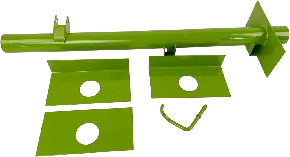
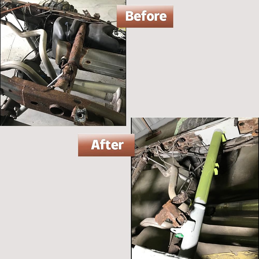
Repairing a rusted frame with original equipment usually requires a complete frame replacement. This frame repair kit allows for simpler replacement of just the failed section with heavy-gauge steel.
Cost-effective fix - this chassis frame repair kit allows you to replace a rusted frame section
Improved design - re-engineered with improved drainage to prevent future corrosion buildup
Durably engineered - built with heavy-gauge steel and finished in weldable primer to resist future corrosion
Direct fit - includes all OE hardware mounting positions for complete installation
Fits:
1999-06 Chevrolet Silverado 1500 Rear Forward Frame Repair Kit
2007 Chevrolet Silverado 1500 Classic Rear Forward Frame Repair Kit
1999-04 Chevrolet Silverado 2500 Rear Forward Frame Repair Kit
1999-06 GMC Sierra 1500 Rear Forward Frame Repair Kit
2007 GMC Sierra 1500 Classic Rear Forward Frame Repair Kit
1999-04 GMC Sierra 2500 Rear Forward Frame Repair Kit
Instructions
NOTE: The photos included show work done on a frame that has been removed from the
body. Although this looks somewhat different than work done on a frame attached to the
truck body, the steps will remain the same.
STEP 1: Remove the truck bed, safely raise the vehicle off the ground, and suitably
support the vehicle. NOTE: CONSULT THE VEHICLE'S OWNER'S MANUAL OR SHOP
MANUAL TO DETERMINE THE PROPER WAY OF RAISING AND LOWERING YOUR VEHICLE.
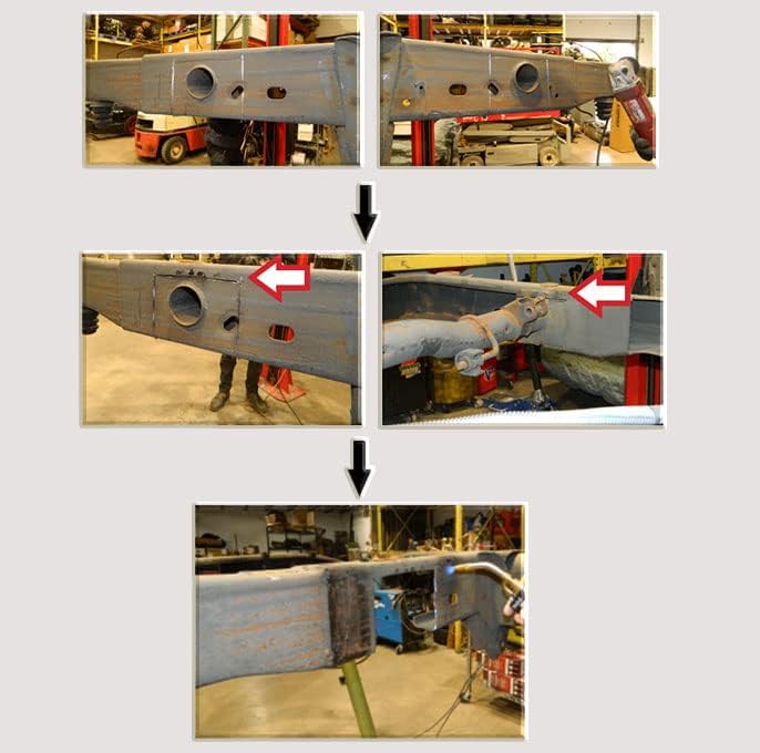
STEP 2: Using a cutting wheel, cut around
the top and sides of the ends of the crossbar
on the frame, on both sides of the frame.
NOTE: Do not fully cut and remove the
crossbar yet.
STEP 3: Before completely removing the
crossbar, mark off where the center of the
tube goes with a permanent marker, to
accurately place the replacement tube later.
STEP 4: Using a cutting wheel, finish cutting
around the bottom and inside of the ends of
the crossbar on the frame, on both sides of
the frame. Once complete, the cut will go up
and over the tube on the outside and inside
of the frame, on both sides of the frame.
NOTE: Do not cut the frame completely in
half (note that the top of the frame is not cut
in the photos). Make sure the vehicle frame
is properly supported, because the frame
will want to twist or bend when the crossmember is removed.
STEP 5: Once the cuts are complete, remove
the crossbar from the frame.
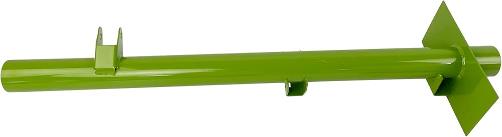
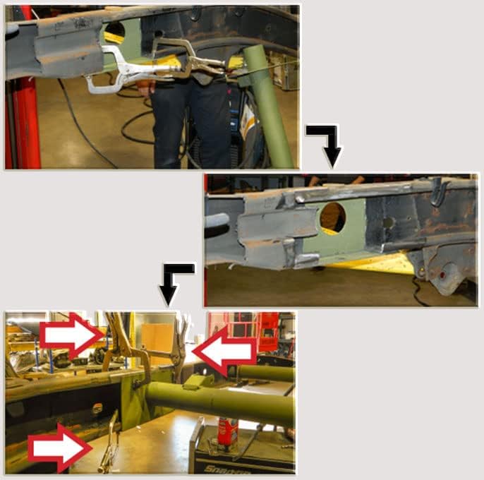
STEP 6: Place the replacement crossbar
in place of the removed one. Hold the
replacement crossbar in place to the frame
with c-clamps or vice grips. Then, using a
permanent marker, mark off the section
of the frame around where the crossbar
attaches to the frame (on both sides
of the frame).
STEP 7: Remove the replacement crossbar
and the c-clamps or vice grips. Then, using
a handheld torch and paint scraper, clean
down to the bare metal where the crossbar
will attach to the frame, on both sides of the
frame, for a proper and strong weld.
STEP 8: If necessary, using a flap wheel disc,
sand the outside of the frame to clean
for welding, on both sides of the frame.
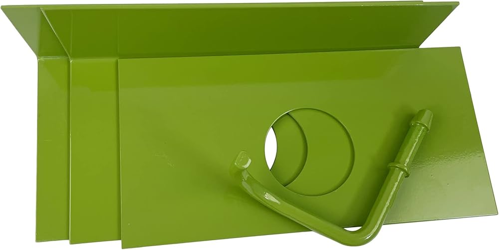
STEP 9: Using c-clamps or vice grips, place
the outer plates to the outside of the frame,
on both sides of the frame.
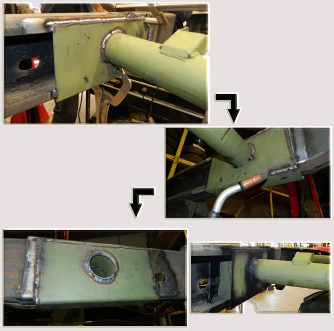
STEP 10: Using a welding torch, weld the
outer plate to the outside of the frame on
both sides of the crossbar.
STEP 11: Hold the tube and inner plates
in place on both sides of the frame. Then,
using a permanent marker, mark off the
section of the frame around the inner plates
(on both sides of the frame), so you can
clean the frame underneath the inner plates
down to the bare metal.
STEP 12: Remove the tube and inner plates
from the frame. Then, using a flap wheel
disc, sand the inside of the frame to clean
for welding, on both sides of the frame.
STEP 13: When you are finished, the inside
of the frame on both sides should be clean
as shown.
STEP 14: Replace the inner plate and tube,
and hold in place using c-clamps
or vice grips.
STEP 15: Using a welding torch, weld the
inner plate to the inside of the frame, on
both sides of the frame. Then, weld around
the tube to the inner and outer plates, on
both sides of the frame.
STEP 16: When finished, the weld on the
inner and outer plates and around the tube
should look like the photos shown.
STEP 17: Once the tube is in place, attach
the included exhaust hanger in the same
location as the OE.
STEP 18: Be sure to paint all bare metal
surfaces to prevent any rust or corrosion.
STEP 19: Safely lower the vehicle. NOTE: CONSULT THE VEHICLE'S OWNER'S MANUAL
OR SHOP MANUAL TO DETERMINE THE PROPER WAY OF RAISING AND LOWERING
YOUR VEHICLE.

 -15%
Engine Harmonic Balancer Crankshaft Pulley Compatible with Honda Accord 03-05 Civic 02-05 Element 03-06 CR-V 02-06 Acura TSX 04-08 RSX 02-06 L4 2.0L 2.4L 594-298 13810PNA013
SAR 156
-15%
Engine Harmonic Balancer Crankshaft Pulley Compatible with Honda Accord 03-05 Civic 02-05 Element 03-06 CR-V 02-06 Acura TSX 04-08 RSX 02-06 L4 2.0L 2.4L 594-298 13810PNA013
SAR 156
 16pcs Small Block Chevy 1.5 3/8 Stainless Steel Roller Rocker Arms Sbc 305 350 400
SAR 587
16pcs Small Block Chevy 1.5 3/8 Stainless Steel Roller Rocker Arms Sbc 305 350 400
SAR 587
 Engine Cylinder Head Head Bolts Set ES72196 Compatible with Buick Lacrosse Regal Verano For Chevrolet Cavalier Equinox Impala Malibu For Pontiac G5 Saturn L300
SAR 87
Engine Cylinder Head Head Bolts Set ES72196 Compatible with Buick Lacrosse Regal Verano For Chevrolet Cavalier Equinox Impala Malibu For Pontiac G5 Saturn L300
SAR 87
 Power Steering Gear Box Assembly Fits Dodge Ram 2500/3500/4000 Pickup 1994-1996 27-7556
SAR 891
Power Steering Gear Box Assembly Fits Dodge Ram 2500/3500/4000 Pickup 1994-1996 27-7556
SAR 891