- Shopping, made easy.
- /
- Get the app!
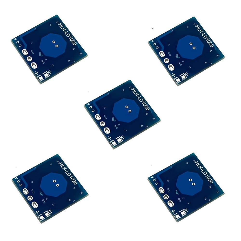
Driver power supply design considerations
Be sure to use the output voltage, current and ripple coefficient of the drive power up to standard, drive power is not stable, electromagnetic radiation is too strong, will cause the ra¡¤dar module false alarms, no perception, cycle of self-starting and other phenomena.
Matching drive power supply should be in 3.3~12V, drive current is not less than 1mA (or 100mA), power supply ripple amplitude should be controlled within 100m V, frequency fluctuation amplitude should be small.
Drive power and ra¡¤dar module assembly, should avoid ra¡¤dar module bottom or antenna surface, facing the drive power module, and should try to stay away from the drive power module inside the rectifier bridge, switching transformer and other industrial frequency interference devices.
Precautions
The device assembled with ra¡¤dar module should be installed far away from ventilation ducts, fire pipes, drainage pipes, mechanical vibration or large metal equipment and other strong vibration objects, because it will affect the ra¡¤dar reflected waves and detection and perception effects.
It is strictly prohibited to work with electricity, so as to avoid action errors, connecting the wrong, burned circuit or electric shock; avoid installation in the sun and rain to prevent damage and affect the service life.
The device must be installed far away from the electromagnetic field place, so as to avoid electromagnetic interference to produce false action; should also be installed far away from the object fixed rotation or swing (such as electric fans, swinging leaves, wind drying clothes, etc.) place, so as to avoid false action.
When several devices with built-in ra¡¤dar modules are fixedly installed, the distance between each device should be ensured to be >0.5m.
 JMT ADT-R37 PCIe5.0x16 to 4-Port U.2/EDSFF Hard Disk Split Card 4x128Gbps 1 to 4 Expansion Adapter Compatible with Gen3/Gen4/Gen5 (R37A 4.0, to 4* U.2)
SAR 397
JMT ADT-R37 PCIe5.0x16 to 4-Port U.2/EDSFF Hard Disk Split Card 4x128Gbps 1 to 4 Expansion Adapter Compatible with Gen3/Gen4/Gen5 (R37A 4.0, to 4* U.2)
SAR 397
 JMT JY-i9 M.2 M Key Magnetic 2242 Enclosure 10Gbps USB 3.2 with AC Data Cable Compatible with M.2 NVMe M Key SSD
SAR 115
JMT JY-i9 M.2 M Key Magnetic 2242 Enclosure 10Gbps USB 3.2 with AC Data Cable Compatible with M.2 NVMe M Key SSD
SAR 115
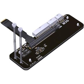 JMT ADT-M43SG M.2 NVMe M Key to PCIe4.0 X16 External Bracket 64Gbps Full Speed for Graphics Card Above 1660 (M43SG-50cm)
SAR 334
JMT ADT-M43SG M.2 NVMe M Key to PCIe4.0 X16 External Bracket 64Gbps Full Speed for Graphics Card Above 1660 (M43SG-50cm)
SAR 334
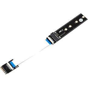 JMT M.2 NGFF Key M to Key A+E Extension Cable Adapter Card with High Speed FPC Cable for 2230/2242/2260/2280 Laptop SSD Adapter
SAR 109
JMT M.2 NGFF Key M to Key A+E Extension Cable Adapter Card with High Speed FPC Cable for 2230/2242/2260/2280 Laptop SSD Adapter
SAR 109