- التسوق ، اصبح سهلا.
- /
- احصل على التطبيق!
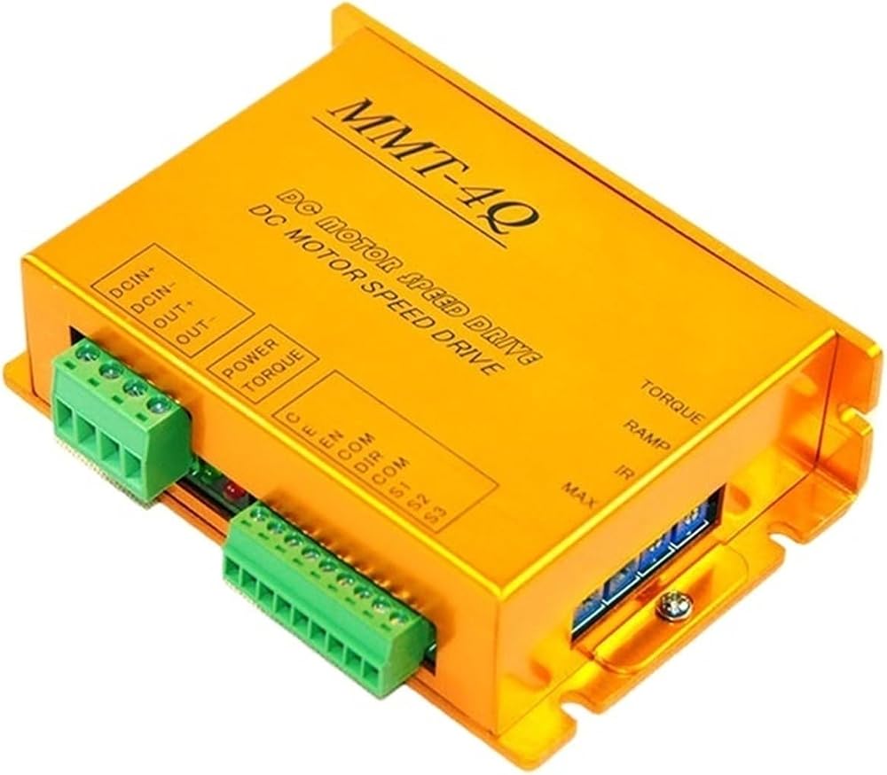
Speed Control
Soft start soft stop pwm brushed controller 20A 24v motor speed control forward reverse for DR equipment
Model: DC24/20BL-4Q02B
1. PULSE WIDTH MODULATION
Motor runs quieter, with greater efficiency and less maintenance, longer life.
2. SMT technology, small size
3. Low noise during operation, high efficiency, and low maintenance cost which better enhance the service life of motor.
4. ENABLE / BRAKE / DIRECTION TERMINALS
Choose a function by simply opening or closing a dry contact or through an open collector transistor.
5. STATUS LEDs
Power and Fault LEDs provide a visual status of the drive.
6. Forward and reverse can be set separately
It doesn't need external reversing contactor and will not result in electric motor parts or other components overheating or burning down.
7. Output current can be set
8. compensatio
9. Standard analog control mode: Analog:0-5V or potentiometer
10. Over voltage & less voltage protection
11 OVER TEMPERATURE PROTECTION
Drive will fold the output power back to prevent from overheating. Drive will fault if it still remains too .
Specification for DC24/20BL-4Q02B
Input voltage range
24V-48V(if you need 12V, kindly leave a message when place the order)
Output voltage
24VDC, adjustable
Max output current
20A
Operating mode
Speed mode, mode
Control ways
PWM, Potentiometer, analog signal 0-10V (if you need 0-5v signal control, please leave a message when place the order)
Protection
Abnormalitise like over current, overheating, over voltage, less voltage and short circuit will start the protection function.
Temperature protection
When the temperature is 70, the controller will reduce output by overheating protection and stop output.
Working Temperature
-10 -- +50
Ambient humidity
Relative humidity less than 80RH
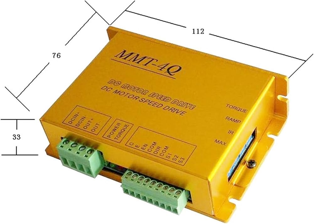
Size
L*W*H = 112*76*33 mm
Weight
250g
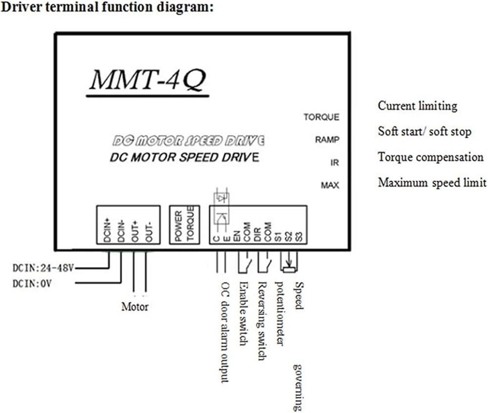
Description of control terminal's functions:
1. EN (enable control)During motor operation, simply connect/ disconnect EN with COM to control the start and stop of motor
Connect EN terminal with COM, EN terminal is effective, at this time regulate external speed potentiometer and motor is in normal operation.
EN terminal suspends in the air or is not connected, EN terminal is invalid; circuit of controller is blocked and motor stops.
2. DIR (direction control)During motor operation, simply connect/ disconnect EN with COM to reverse the motor rotation. It doesn't need external reversing contactor and will not result in electric motor parts or other components overheating or burning down.
Connect DIR terminal with COM, DIR terminal is effective, motor is in negative rotation.
DIR terminal suspends in the air or is not connected, DIR terminal is invalid; motor is in positive rotation (runs in opposite direction as above mentioned).
3. C E (OC door alarm output)The internal design of "OC door alarm output" is that over-current signal is transmitted through an opto-coupler to give alarms. When over-current is detected on the controller, over-current signal will be immediately sent to diode of opto-coupler for break over and then transmitted to C, E ports. The client can wire as their own requirements, as shown in Figure 1, connect to over-current indicator,
Figure 2, relay actuation after over-current to give alarms.
Internal wiring diagram of "OC door alarm output" is shown as follows:
OC door alarm output
Alarm indicator output
Figure 1: Wiring description of alarm indicator output
Relay coil
Figure 2: Wiring description of alarm relay output
4. S1 S2 S3 signal output terminalSuch controller has two control modes of external speed potentiometer control and external analog quantity input. Description of various terminals is as follows:
S1 Terminal: external power+10V ,
S2 Terminal: signal input terminal
S3 Terminal: GND (grounded).
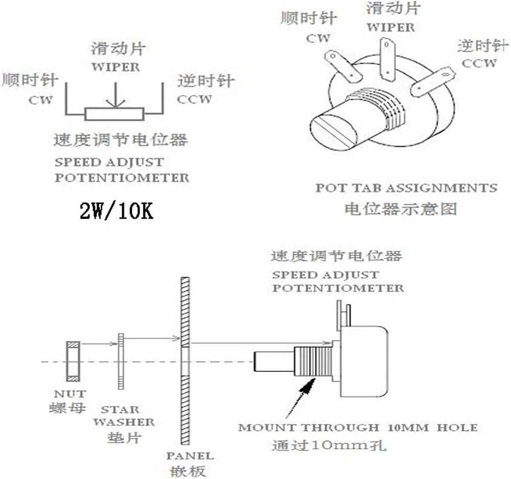
4.1 When external speed potentiometer control is used, S1, S2, S3 terminals shall be connected with external potentiometer as shown in VI. Driver terminal function diagram to regulate external potentiometer for speed governing
4.2 When external analog quantity input control is used, speed can be controlled through S2 and S3 input, both 0-5V and 0-10V are OK.
Description of indicator:1. POWER (Green) power indicatorIf the controller is charged, this indicator lights up to indicate that controller is under normal operation.
2. (Red)over-current indicator turns red to indicate that output current of the controller exceeds client's preset current, and the controller will automatically limit the output current to such value.
Regulation description of functional potentiometer:
MAX (maximum output voltage limit)It is used for limiting motor's maximum speed (limit the max output voltage). Increase in clockwise rotation and decrease in counter clockwise rotation.
IR ( compensation)Regulate "IR" enable motor work under different loads and keep revolving speed constant (normally default is 0), Increase in clockwise rotation and decrease in counterclockwise rotation.
RAMP (soft start/ stop)Regulate "RAMP" to set motor's starting and stopping time (1-20 S). Increase in clockwise rotation.
(current limit regulation)Regulate "" to set over-current protection value of the controller; regulating range is 0-20A, Increase in clockwise rotation and decrease in counterclockwise rotation. When reaches over-current limit value, over-current indicator (Red) lights constantly and current is be limited to such value, at this time, continue to regulate the external potentiometer, current value is invariant( i.e. amplitude limiting).
soft start soft stop pwm brushed controller 20A 24v motor speed control forward reverse for DR equipment
==========
Model Number : DC24/20BL-4Q02B
Motor Type : Motor
Input voltage : 24V-48V
Output voltage : 24V, adjustable
Max output current : 20A
Control signal : potentiometer, 0-10V, PWM
Reversible : Yes
Soft start/stop : Yes
Applicable : brushed motor, pmdc motor
 DP-301-1 DC310V 30W 30001R/MIN محرك مضخة الصرف لاستنزاف الطبق G1 S1 أجزاء غسالة الصحون
SAR 511
DP-301-1 DC310V 30W 30001R/MIN محرك مضخة الصرف لاستنزاف الطبق G1 S1 أجزاء غسالة الصحون
SAR 511
 1pcs T6861 2/4 سلسلة ترموستات رقمية مروحة مروحة مع شاشة إضاءة خلفية زرقاء كبيرة لأنظمة HAVC (T6861H2WB)
SAR 678
1pcs T6861 2/4 سلسلة ترموستات رقمية مروحة مروحة مع شاشة إضاءة خلفية زرقاء كبيرة لأنظمة HAVC (T6861H2WB)
SAR 678
 yxw50-2e (l) مضخة الدورة الدموية لتجميع محرك مضخة التدفئة غسالة الأطباق
SAR 1,306
yxw50-2e (l) مضخة الدورة الدموية لتجميع محرك مضخة التدفئة غسالة الأطباق
SAR 1,306
 مضخة تصريف مجفف 1PCS لـ DC31-00105C B13-5AN1B120 60Hz 220-240V 15W أجزاء غسالة الصرف الصحي
SAR 447
مضخة تصريف مجفف 1PCS لـ DC31-00105C B13-5AN1B120 60Hz 220-240V 15W أجزاء غسالة الصرف الصحي
SAR 447