- Shopping, made easy.
- /
- Get the app!
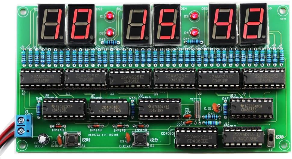
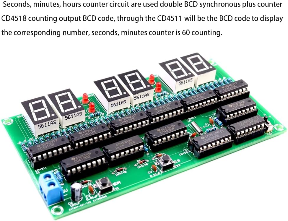
60-binary circuit principle of operation: when the time is 60 seconds, the 4518's ten-bit output of the BCD code is 0110, through a with the gate circuit (CD4581)
connected to the 4518's Q2B and Q3B terminals, when up to 60 seconds, these two terminals at the same time, the output of 1, through the output of 1 with the gate
circuit to the CD4518 to clear, the number of re-counting from 00, and at the same time, to give a sub-signal or time At the same time, a pulse plus 1 is given to the
minute signal or time signal.
The 24-binary circuit works similarly to the 60-binary circuit, except that the signal taken is 24. The BCD code output from the 4518 is 0010 0100, which can be
taken from the Q2B and Q3A terminals of the 4518. The circuit does not have a power failure memory time function, you need to re-calibrate the time after power failure.
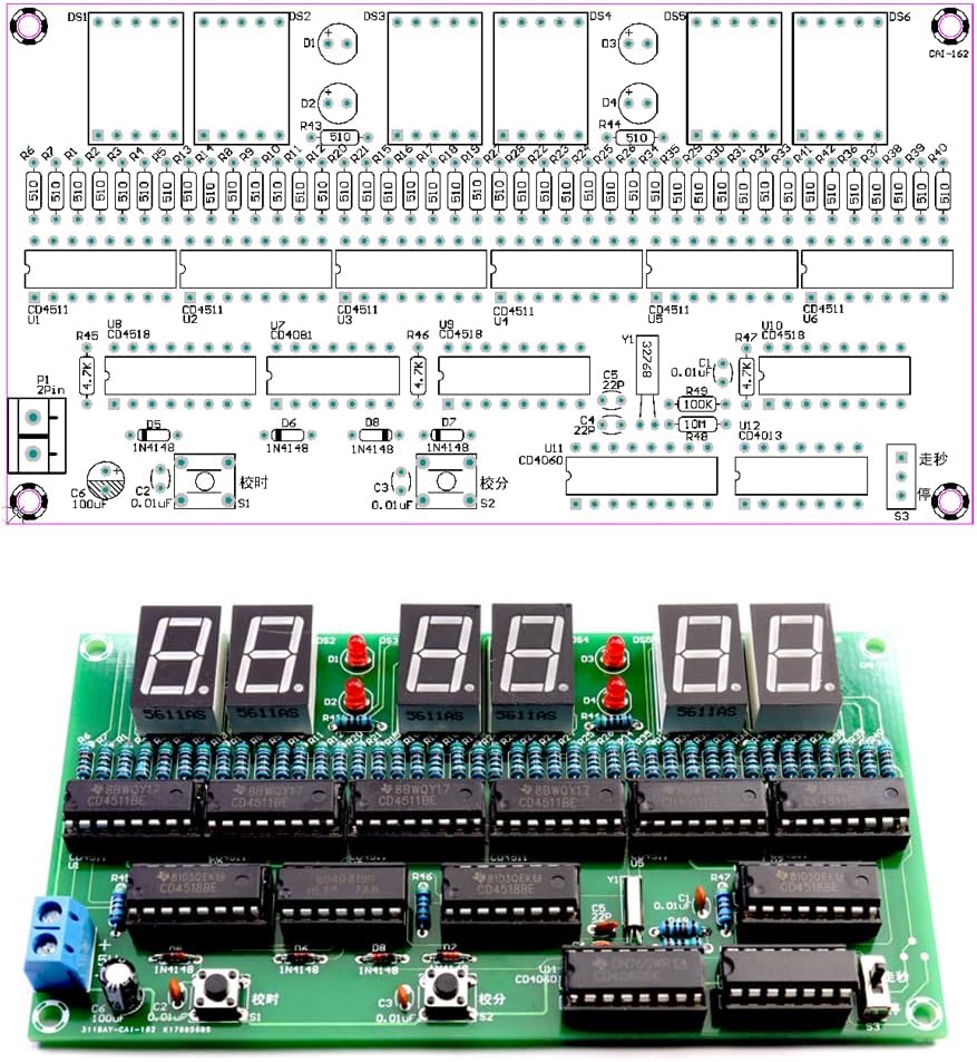
Circuit Installation and Commissioning.
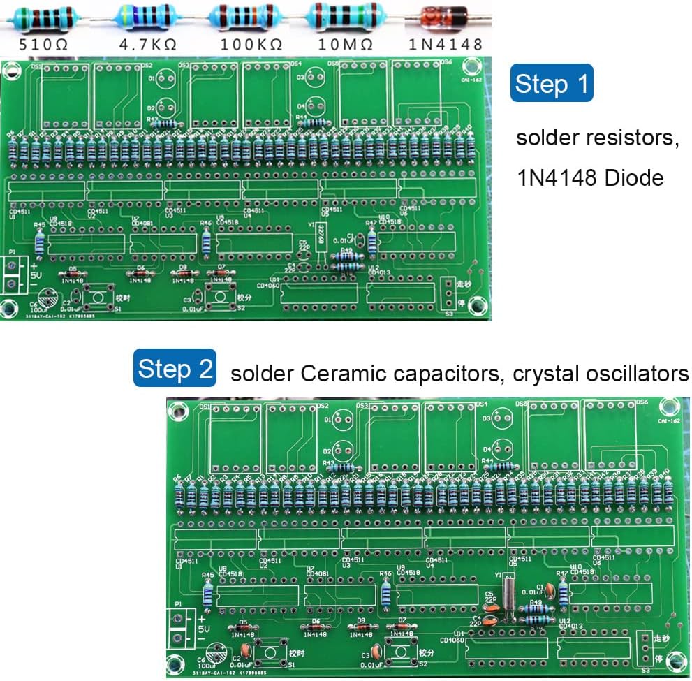
Solder in the order of the component list, install the short component first then the tall component.
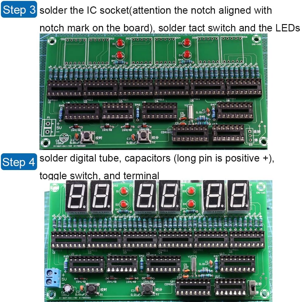
Integrated circuits are soldered The IC holders first, chips are mounted on the socket last.
Components that do not distinguish between pin direction: resistors, crystals, ceramic capacitors, toggle switches.
Components with positive and negative poles:Light-emitting diodes and electrolytic capacitors with long pin are positive, aligned with the position marked + on the board,
and the position of 1N4148 with a black circle is aligned with the position of the white mark on the board.
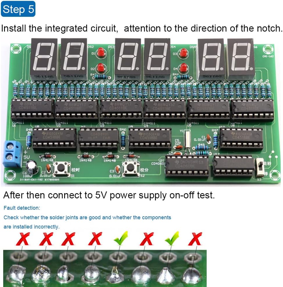
The notch position of the IC holder is aligned with the direction of the notch position on the circuit board, and the notch position of the IC is also aligned with the notch mark on the circuit board.
The flick switch can be loaded normally in the correct position.
Pin order identification: chip text is aligned with their own, from the lower left corner of the first foot is 1 counterclockwise number.
 Insect and Butterfly Habitat Cage Terrarium Pop-up 23.6 Inches Tall with 10Pcs 60Ml Floral Tubes with Rack Holder for Milkweed Cuttings
SAR 131
Insect and Butterfly Habitat Cage Terrarium Pop-up 23.6 Inches Tall with 10Pcs 60Ml Floral Tubes with Rack Holder for Milkweed Cuttings
SAR 131
 -6%
Nautical Brown Wooden Walking Stick Spy Antique Telescope Compass Handle Canes Rustic Vintage Home Decor Gifts
SAR 166
-6%
Nautical Brown Wooden Walking Stick Spy Antique Telescope Compass Handle Canes Rustic Vintage Home Decor Gifts
SAR 166
 Microscope Pocket Handheld Miniscope 80X-200X Portable Microscope with LED Light for Learning Education Exploring (Pink)
SAR 52
Microscope Pocket Handheld Miniscope 80X-200X Portable Microscope with LED Light for Learning Education Exploring (Pink)
SAR 52
 Kids Microscope 200X Magnification, STEM Handheld Digital Science Kit with Rechargeable LED, Portable Educational Toy for Ages 3-12, Birthday for Boys & Girls Yellow
SAR 126
Kids Microscope 200X Magnification, STEM Handheld Digital Science Kit with Rechargeable LED, Portable Educational Toy for Ages 3-12, Birthday for Boys & Girls Yellow
SAR 126