- Shopping, made easy.
- /
- Get the app!
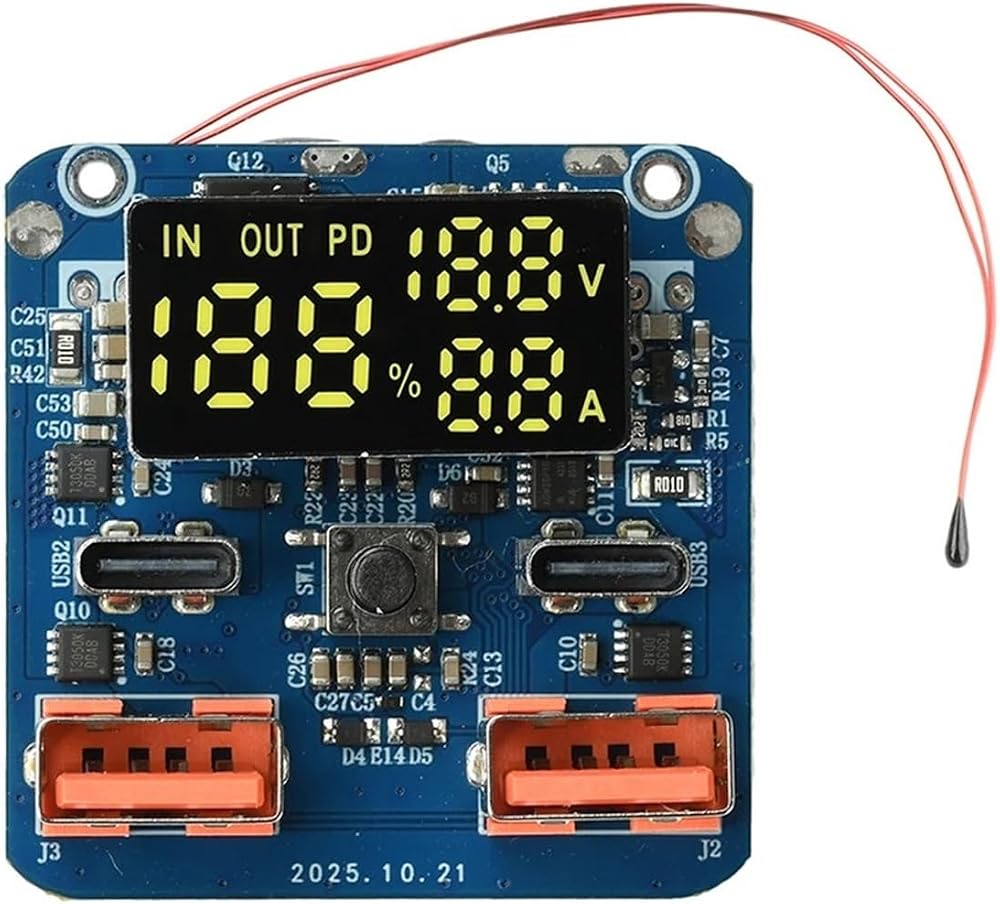
PD 100W Type A
Product Parameters
- Type‑C Interface: PD 100 W, 20 V / 5 A
- USB Port: SCP 22.5 W, 4.5 V / 5 A; 18 W / 20 W, 9 V / 2 A
- Battery level percentage display
- Interface current and voltage display
Notes
1. Do not perform live soldering. When soldering the + and – wires of the mainboard, ensure no power is applied to avoid the vast majority of unexpected situations.
2. The mainboard has only + and – terminals. If soldered while powered, it may easily shake and burn. Please disconnect power before soldering. Connect the mainboard + and – first. The negative terminal of the battery pack should be soldered last. The two wires on the mainboard cannot balance the battery; the balance protection function is provided by the lithium battery protection board.
3. On first power‑up, the battery level may not display correctly but will return to normal after a charge/discharge cycle.
4. The default capacity setting for a single cell is 500 mAh, which may cause inaccurate battery display. This does not affect other functions, and there is no need to worry about overcharging or over‑discharging.
Packing List
1 × Module
PD 100W Type B and PD 100W Type C
Product Parameters
- Type‑C1 Input: 5 V / 3 A, 9 V / 3 A, 12 V / 3 A, 15 V / 3 A
- Type‑C2 Input: 5 V / 3 A, 9 V / 3 A, 12 V / 3 A, 15 V / 3 A, 20 V / 3.25 A
- Type‑C1 Output: 5 V / 3 A, 9 V / 3 A, 12 V / 3 A, 15 V / 3 A, 20 V / 5 A
- Type‑C2 Output: 5 V / 3 A, 9 V / 3 A, 12 V / 3 A, 15 V / 3 A, 20 V / 3.25 A
- USBA1 Output: 5 V / 3 A, 9 V / 2 A, 12 V / 1.5 A (22.5 W)
- USBA2 Output: 5 V / 3 A, 9 V / 2 A, 12 V / 1.5 A (22.5 W)
- Real‑time digital display of battery level, voltage, and current
Frequently Asked Questions
1. Protection board wiring: For a 4S battery pack, starting from the negative terminal, the first positive is B1 (4.2 V, or 3.6 V for Li‑Fe). B2 is 8.4 V, B3 is 12.6 V, and B+ is the positive terminal at 16.8 V. Connect the protection board P+ and P‑ to the mainboard.
2. If the battery does not light up or work after being connected (whether already charged or not), charge and activate it via the C port first. The battery must be charged to activate.
3. After charging activation, the display may show 0 or 100. The first power‑up cannot accurately display the battery level; it returns to normal after charge/discharge cycles.
4. During use, if the battery reaches 80% but cannot be fully charged, or discharges to 20% and then stops, this may be caused by inconsistent cell voltages. In the most severe case, if a cell is fully charged at 4.2 V but drops below 3 V, it can no longer be used.
Precautions
1. Disconnect power before soldering. Solder the mainboard + and – first, and connect the battery pack negative terminal last.
2. The two wires on the mainboard cannot balance the battery. The balance protection function is on the protection board; an additional lithium battery protection board can be added.
Packing List
1 × Module
Please measure your existing part dimensions before ordering to ensure proper fit.
 Turbochef ENC-1114 Filter, Air, Bullet/Encore Ove
SAR 287
Turbochef ENC-1114 Filter, Air, Bullet/Encore Ove
SAR 287
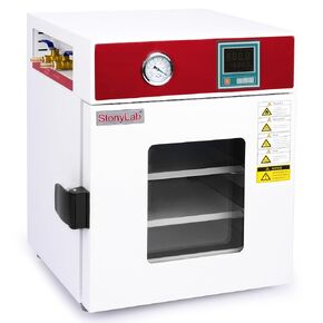 stonylab Digital Vacuum Drying Oven, 0.85 cu.ft, 110V, RT+10-250℃ for Lab Drying and Heating, with Vacuum Gauge and Digital Controller, CE Certified
SAR 6,002
stonylab Digital Vacuum Drying Oven, 0.85 cu.ft, 110V, RT+10-250℃ for Lab Drying and Heating, with Vacuum Gauge and Digital Controller, CE Certified
SAR 6,002
 F11.1 mm x 39.1 mm Microtube Dry Bath Block - 20 x 1.5 ml
SAR 345
F11.1 mm x 39.1 mm Microtube Dry Bath Block - 20 x 1.5 ml
SAR 345
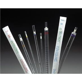 Celltreat 229210 Serological Pipet, 10mL Capacity, Sterile, Individually Wrapped/Dispenser Carton (Case of 200)
SAR 376
Celltreat 229210 Serological Pipet, 10mL Capacity, Sterile, Individually Wrapped/Dispenser Carton (Case of 200)
SAR 376